Introduction
In 2016 I constructed a sturdy See-through Gate to keep the public out of a passageway I share with a neighbour. I’ve written about it here so that anyone requiring a similar sturdy see-through gate can take my ideas of how I built it and use them when building their own.
I did pre-empt this article by taking some photos but I wish I had taken more while constructing the sturdy see-through gate. Consequently I had to make more drawings and diagrams to complement the article.
The Reason I Built This Sturdy See-through Gate
My house is built with a right of way at the bottom of the back garden to allow my neighbours access from their back garden to a side street. This right of way is fenced off from my garden on one side, and from a third party’s house in the side street on the other side. These fences turn this right of way into a passage which we both have access to through our own garden gates.

My neighbour and I had previously discussed the need to keep strangers out of this passage, so we agreed to “take back control” by erecting a lockable gate at the street end for which we each have a key.
We already had tall fencing and solid gates around our gardens preventing us from seeing people in the passage but we could still hear them. The passage was open to the public after all. Not knowing what they were about, we agreed to keep them out by gating it off at the street.
Passage History
When I first moved into my house many years ago it had a low chicken wire fence on my side of the passage and we both had low gates, so people could easily be seen if they entered the passage. When they realised this they didn’t hang around, but a low level wire fence offered little security. So the first 1.8m high fence was built in the 1980’s. My neighbour soon followed by increasing the height of his gate to 1.8m. Then both our gardens were private.
My Previous Experience Building Gates
I have built two garden gates before this one. They were not “see-through” but solid, like doors, and made of vertical pine tongue and groove boards, glued and screwed to three horizontal boards with two diagonal sections, similar to the construction of this sturdy see-through gate. See below:

You may look at this picture and suspect the diagonals didn’t perform well at keeping this gate in shape. I assure you the gate remained true, but the concrete posts to which the gate posts were attached began leaning over with time and a prevailing westerly wind. The wind applied pressure to the side fence which turned the fence at the right side of this gate into a parallelogram shape. All the posts developed a leaning attitude.
These old gates weren’t exactly the same size as my sturdy see-through gate, but were about 90cm wide and 1.8m tall. During their life one survived a car crashing into it which ripped the hinge post off the house wall. That gate survived well and only suffered minor bruising. It was refitted to the repaired fence which it outlived, and was eventually passed on to another user.
My two new solid gates were built professionally by my fence erector: ABBEY DECKING SYSTEMS, GATES & FENCING SERVICES, a Derbyshire County Council Trusted Trader (according to their website declaration).
Action Began When I Had A New Fence
In 2016 I had a house extension built on a plot in my back garden surrounded by my garden fence. The fence was old and ready for replacement and part of it had to be removed to accommodate the extension. So I had a new fence erected. I also had to remove two sheds from the plot and build a new one in the corner of the garden.
The new shed couldn’t reasonably be put up before the fence was replaced. So I had the greater part of the fence replaced before the extension was built and the remaining four panels afterwards.
When I had the new fence put up, I ensured a gate could be accommodated at the street end of the passage. I asked the fence erecter to put a wooden fence post beside two concrete fence posts he was planting. They were in a corner where the passage meets the street and I needed a wooden post to screw my gate’s hinges to. Go and see, “The plan views of the hinging of the See Through Gate.“
You might wonder why I didn’t ask the fence erector to make this gate. Well there would have been the labour charges and I would need to spend time conveying my ideas about its design. I needed him to do his work quickly whereas I could build this gate in my own time, after all it had waited 30 years already.
My Sturdy See-through Gate Specifications
I decided the gate must be:
- “see-through”,
- strong enough to withstand attempts to climb over it,
- difficult to break down by manhandling it,
- weather resistant,
- easy to unlock in frosty weather,
- difficult to break open at the hinges,
. . . but it must not:
- trap animals,
- swing out into the street,
- use the side street neighbour’s fence for support, latching, etc..
. . . and it must have:
- a means (a hook) to hold it completely open,
- a secure lock (with two keys) accessible within the passage.
Gate Dimensions:
- Height: 180cm above ground (including leg),
- Width: 114.5cm,
- Thickness: 5.5cm without furniture¹.
Why This Gate Must Be See-through
One important specification from my point of view is a requirement for the gate to be “see-through” so that the passage contents can be seen from the street. I don’t want to go into the passage one day and find something unpleasant dumped there after it has been thrown over the gate.
Nor do I want to find a trapped animal in the passage. So it is important to have a gap under the bottom of the sturdy see-through gate for animals to escape. Some might think it best to keep animals out by having no gap, but I know cats climb over fences and jump down without realising they may not be able to climb back up. It’s also important to have gaps under gates to give access to hedgehogs.
I chose to leave a 10cm gap at the bottom. There is also a 55mm gap between the vertical slats which offers extra space for a cat squeezing through. So far there hasn’t been anything but man-made litter and leaf litter gathering in the passage. Those items are mainly driven in by the wind.
If I want to check the state of the passage I just have to walk down the street and look through the gate. I don’t have to unlock my garden gate to do it.
Design Details And Technical Drawing
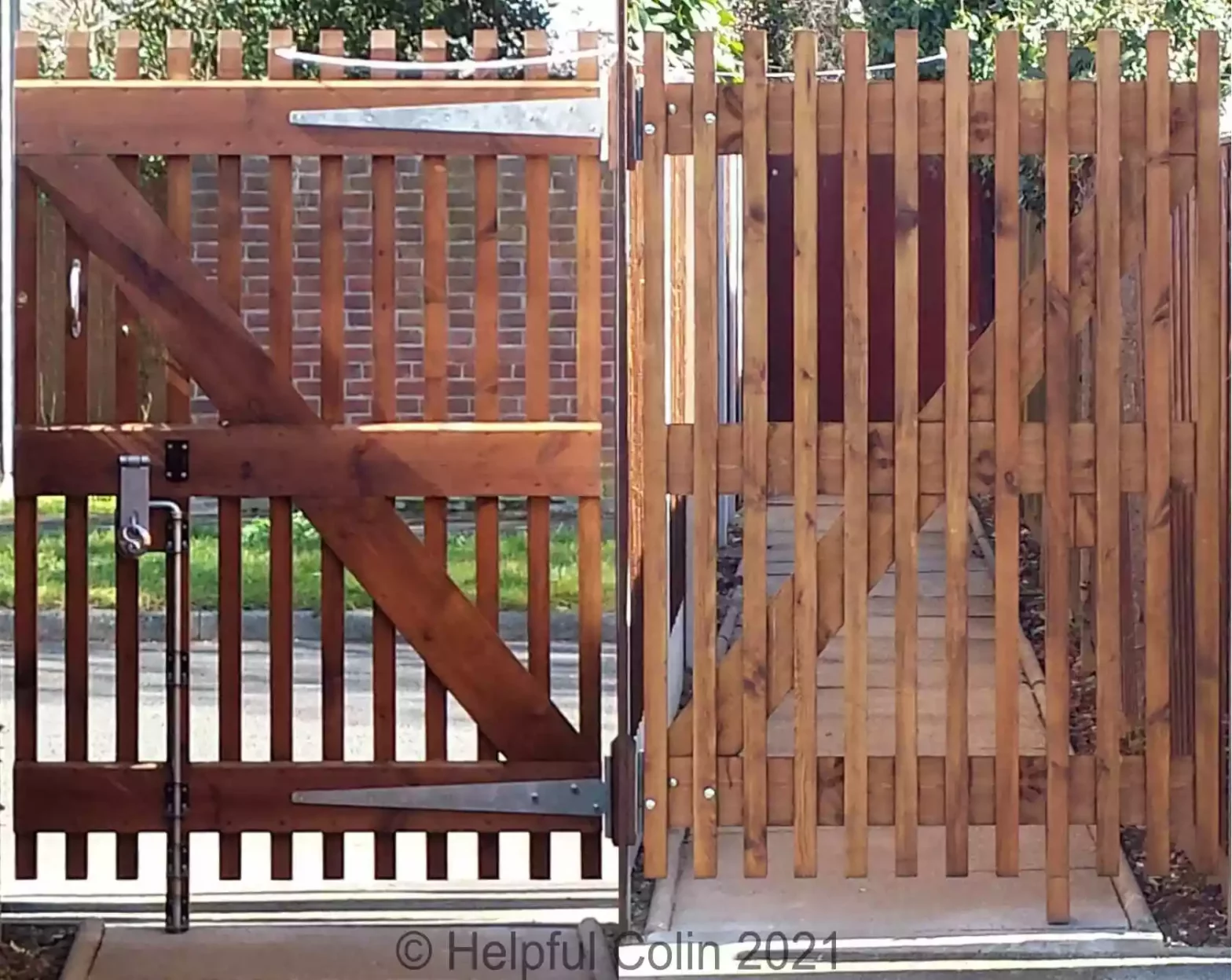
The featured image for this article shows photographs of both sides of the sturdy See-through Gate in situ. You can see it again here:

In these pictures the gate restraint is a synthetic cord. That was sufficient until the ultraviolet light from the sun perished it. It’s now been replaced by a Safety Chain.
Below is a Technical Drawing of the sturdy see-through gate in First Angle Projection. In practice it’s all painted the same colour, but in the drawing separate pieces of timber and angled surfaces have different colours to distinguish them.
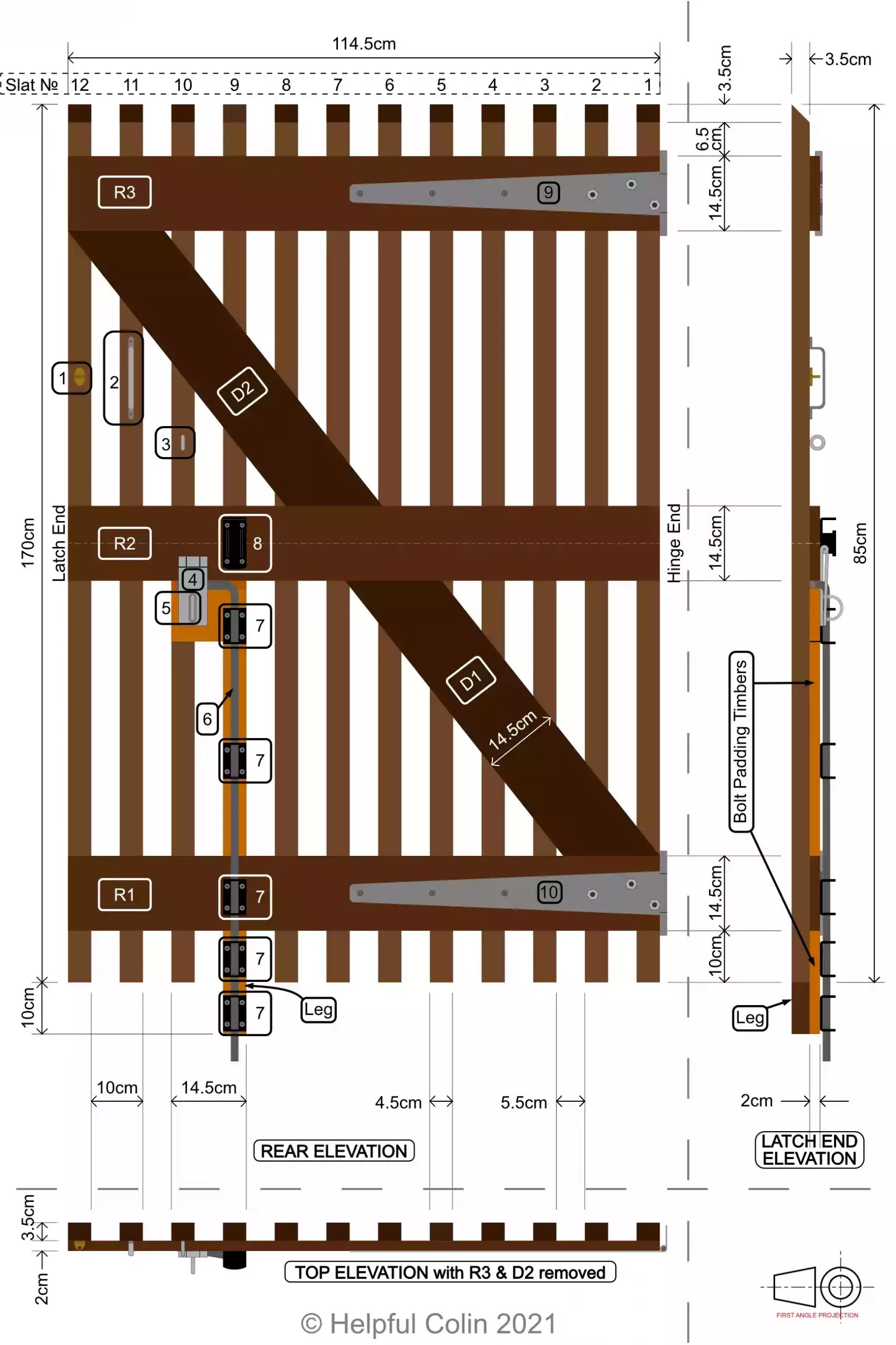
(Look at the Key for a description of numbered gate furniture parts.)
NOTE: Items of gate furniture1 may not be drawn 100% accurately, but are a good representation.
Key For The Sturdy See-through Gate Drawing
Wooden Parts:
- Slats № 1 to 12.
- Rails № R1 to R3.
- Diagonal Spars № D1 & D2 (to give triangulation).
- Leg and Bolt Padding Timbers.
Gate Furniture:
- Eye for hook to hold the gate open.
- Handle to hold when moving the gate.
- Eye to hold the padlock while the hasp and bolt are being opened.
- Hasp for holding the bolt in the closed position.
- Eye to hold the padlock while it’s locking the hasp and bolt.
- Bolt for holding the gate closed by engaging a hole drilled in a concrete slab on the ground.
- Five Bolt Guides.
- A part on which to rest the bolt when it’s lifted into the open position, and to keep it captive.
- Upper/top hinge.
- Lower/bottom hinge.
My Sturdy See-through Gate Width
I chose to make a sturdy see-through gate using wooden slats spaced apart. Then someone standing in the street can see through those slats into the passage and check the situation there.
My sturdy see-through gate had to fit in the 118cm span between the wooden hinge post and the fence on the other side of the passage.
The Spacing of The Slats
The slats are a strengthening feature of the gate, not just some flimsy boards attached to a stronger frame. So I made them from twelve pieces of timber with a 45mm × 35mm cross section. (A convenient size available at the timber merchant.)
By placing the slats at 10cm intervals they are 55mm apart when their 45mm width is placed flat on the rails. Consequently twelve slats make up the desired gate width of 114.5cm.
There are 3.5cm left for hinges and padding blocks when fitting the gate in the 118cm space.
My Sturdy See-through Gate Height
The top of the gate needed to be level with the top of the street fence panels. With a 10cm gap for animals to escape at the bottom the gate became 170cm high except where I provided a leg where it was 180cm high.
My Sturdy See-through Gate Thickness
The gate consists of vertical slats fixed to horizontal and diagonal 20mm boards. The horizontal boards space the slats apart and the diagonal boards give triangulation to the gate to keep it in shape. Strength is given by fixing the timbers together with wood screws and waterproof adhesive.
The total thickness of the wooden structure, without metal furniture, is 55mm. The slats being 35mm thick and the rails being 20mm.
Ensuring The Open Gate Doesn’t Restrict The Passage Width
Gate furniture1, e.g. bolt, hasp, hook & eye to hold the gate open, have to be taken into account when the gate is open. If they make the gate too fat it would jut out into the passage.
The padding blocks between the hinges and the post have their thickness adjusted to set the gate hanging vertically. Their thickness also affects the space behind the gate when it’s open. They can help the open gate rest parallel to the fence on my side of the passage.
I think it best if a gate in a passage opens as wide as possible, at least parallel to the sides of the passage else it may obstruct passage traffic.
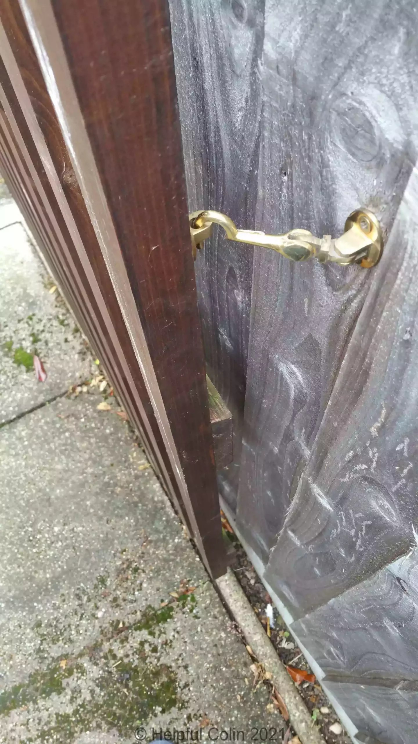
The space behind the open gate is also affected by the length of the hook used to hold it open. One of the shortest I could find was a brass hook intended for internal use. Being brass with brass screws it’s surviving well outdoors.
When the gate is hooked back against my fence the gap behind it at the widest point is >6cm. But if I look at the ground alignment the gate hangs over the edgings of the path and doesn’t take up any space over the slabs forming the path. Also when the gate is hooked to the fence the hook isn’t perpendicular to the fence, it has an angle of 45°. This pulls the gate in towards the fence a bit more. See below.
The Construction Of My Sturdy See-through Gate
Buying The Timber
I went to my local wood yard (timber merchant) who deals mainly in softwoods (pine, etc.). I told him approximately what sizes I required and he advised what widths and thicknesses are available. As a result I ordered:
I chose lengths which I could work with and which would also fit in my car.
After paying I took my receipt to the sawyer in the yard. He could see what sizes were actually available and again discussed how the timber might best be cut. At this stage any waste is given to me because I have to buy the entire length. This way the woodyard doesn’t accumulate waste. The extra timber is often useful in other projects.
I was fortunate that all the timber I bought was straight square and flat. That prevented the gate from having any bends or twists in it after construction. Even five years later it doesn’t appear to be warped.
Cutting The Timber To Length
I had all the slats cut to length and the boards cut oversize at the wood yard. Then when I got the slats home I just had to cut their tops to 45° To give them a slope for rain to run off, and make them feel uncomfortably sharp to anyone trying to climb over the gate.
I cut the three horizontal boards accurately myself avoiding placing knots at the end of the boards. The two diagonal boards were cut much later during assembly as their dimensions and angles were not accurately known at the start.
Marking Out The Timber Ready For Assembly
References are made to the front and back of the gate and its parts. I consider the front to be the side facing the street, the side the public see, which should be made most presentable. That leaves the back being the side visible from within the passage.
Marking The Slats To Align With The Rails
The slats are presented for marking with their 4.5cm wide backs uppermost and chamfered ends at the top. See the diagram below.

The slats are all side by side on a flat surface with their tops and bottoms aligned so they form a neat rectangle. They can be held together with a sash cramp (or similar) to prevent them moving while pencil lines are drawn 10cm from each end. Their combined width is 54cm.
Slats 1 and 12 are also marked on their outside edges with a line midway. This line is used when the central rail has to be fixed and centralised.
Marking The Rails To Align With The Slats
The 114.5cm long boards used for the rails are marked on their edges using a steel tape measure and continued across all three boards using a square. The lines are spaced at, 4.5cm, 5.5cm, 4.5cm, 5.5cm, etc., intervals from one end to the other.
The boards are clamped in a workmate with their ends and edges aligned while being marked. A steel tape is hooked over the left end and the boards are marked at the measurements shown in the diagram below:

Once one edge is marked the boards are turned over and realigned in the workmate with the unmarked edges uppermost and the previous left ends still on the left. These edges can be marked in the same way others. This requires the boards ends to be cut perfectly square in order to get both edges marked opposite each other. The more accurate, but time consuming, method is to extend the marks from one edge to the other by using a square. The latter method can at least be used to make checks that both edges marks are opposite each other.
How To Avoid Some Marking Inaccuracies
When doing this repetitive marking out it’s important to make sure that the last 4.5cm space is indeed that. The lines may have gradually got closer or further apart depending on how their positions are measured.
Cumulative inaccuracies can occur when a short ruler is used to repeat the measurements 4.5cm + 5.5cm + 4.5cm + 5.5cm, etc.. This is based on the concept that individuals, whilst not marking at exactly the correct measurement on the ruler each time, may mark at the same point on the ruler. So if their first measurement is a little larger than needs be, so might all their measurements be.
If a long ruler or steel tape spanning the full width of the gate is used to mark at 4.5cm, 10cm, 14.5cm, 20cm, 24.5cm, . . . , 100cm, 104.5cm & 110cm, there won’t be a cumulative issue.
I think that if the spacings are not exactly the same that won’t get noticed, but if the slats aren’t parallel that will be noticed.
How The Fixing Screws Are Utilised
Apart from the glue, the gate is held together by countersunk wood screws which hold the wood in position while the glue sets. They are not removed after the glue has set so they continue to give added strength. They are inserted through holes drilled in the rails and diagonals then screwed into the slats. The screw heads are only seen on the back/passage side of the gate leaving the front/street side of the gate unblemished.
Marking The Screw Holes In The Rails
Having marked the timber where rails and slats cross, I marked the many screw holes in the rails with a cross. Then I pressed a steel point into the centre of each cross to make it easy to centralise a pilot drill when I bored the hole.
Positioning The Screws
I chose to have all screws 20mm from the edge of the boards and aligned with the centre of the slats. So the first holes are 22.5mm from the ends of the boards and then they repeat at 100mm intervals.
Drilling The Screw Holes In The Rails
Screws Used
The screws I used all over the gate to hold boards onto slats were 4mm diameter × 50mm long (2″ × №8) countersunk Posidriv™ wood screws.
Hole Size
The final hole size is 4mm diameter.
Hole Drilling Process
The complete hole drilling process is listed here:
- Mark the holes with a small cross,
- Press a steel point in the wood at each cross to centre a pilot drill,
- Drill pilot holes at the marked locations,
- Enlarge the pilot holes to full size,
- Counter sink any holes passing through knots (see Note 2 about drilling holes below),
- Sand the back of holes (or touch them with the countersink bit) to remove any splinters or burrs left by drilling.
Notes about drilling holes
- Items 2 & 3 help to keep the hole exactly in place. When not done the final diameter drill may start to wander and the finished item won’t look so good.
- Since soft pine is being used here countersunk screws will pull themselves into the wood when tightened. So countersinking holes is not generally required except where the hole starts off in a knot. Knots are so hard the screws won’t pull down into them and will remain proud.
Fixing Top & Bottom Rails To Slats 1 & 12
My Alternative Bench
Since the gate was much bigger than any bench/workmate I possessed, I had to find an alternative surface to rest it on while I assembled it. I chose to rest the slats across the straight backs of two similar teak garden seats.
First I had to space the seats apart by a suitable distance and make sure both top edges were more or less level and exactly parallel with each other from a vertical perspective. This required me to move them around on the lawn until their legs were resting in the best place.
The diagram below shows the end-on view of the Garden Seats with the gate resting on them from Slat 12 end. Only the bottom and top rails R1 & R2 are shown in position. The middle rail, diagonals and leg have not been fixed in place at this stage.

The Glue I Used
I glued the wooden parts of the gate together with waterproof Gorilla Glue. This is a resin based adhesive which sets after it has been activated by water. Joints need to be clamped or screwed because the adhesive expands as it sets and would otherwise push joints apart. So I used the countersunk wood screws (already mentioned) to hold parts in place while the glue set.
Wet glue can be removed from joints it has oozed out from with a damp cloth. After it has set it can be cut away with a knife.
How I Screwed & Glued All The Gate’s Parts Together
With some things I make that require screwing and gluing I assemble them completely with screws, before gluing, to make sure all parts fit correctly. In this case there are very many screws which would require unscrewing again to apply adhesive. So I didn’t do a 100% pre-fit.
Fitting Rails R1 & R3 To Slats 1 & 12
I decided to create a gate sized frame with two rails and two slats. The intention was to set the gate’s shape and make the frame flat ready to receive all the other parts later.
So, with 8 × 4mm × 50mm CSK wood screws, I:
- screwed R1 to Slat 1,
- then R3 to Slat 1,
- then R1 to Slat 12,
- then R3 to Slat 12.
The timber I used was untwisted so the construction lay flat across the garden seats as shown below. I used a square to true up the joints.

When I was satisfied with the fitting I removed the slat at one end and applied the Gorilla Glue to the slat where the boards would fit. Then I wet the back surfaces of the boards, where they would overlap the slat, with a wet rag. I then put the screws back and tightened them, before doing the same with the other slat.
When completely reassembled I checked that the angles between the boards and the slats were right angles with my square. I then checked the gate assembled so far was still lying flat across the garden seats. That was done by sighting the rails with each other to check they both looked parallel. I also checked that the four items fixed together at this stage didn’t rock on the backs of the garden seats.
Adding The Other Ten Slats (2 to 11)
Once those four pieces were well and truly fixed I added the other slats one by one. The existing assembly has to be lifted a little to put each slat under the rails.

I temporarily fixed each slat without adhesive and just one screw in each rail. By screwing the rails to the slats dry it’s possible to get a good alignment. (These first two screws then re-align the pieces when the slippery glue is in between.) I made sure they were well aligned using the lines I had drawn on the slats and rails before unscrewing, gluing and reassembling with the original two screws.
The other two screws were added when I was happy with the alignment. I rechecked the alignment after each stage of assembly. A straight edge can be used to check all slats are in line along the top and bottom of the gate.
Correcting Misalignment
Misalignment can happen when a wood screw is first turned to pierce the slat it’s being screwed into. Hard and soft grain in pine runs side by side and the point tends to drop into the soft areas. If the screw won’t start in the right place the pieces might have to be clamped in place while the screw is driven in. A short pilot hole might have to be used. If it’s just a little bit out when the screw is finally tightened, tapping the wood with a rubber mallet might nudge it into alignment before fully tightening it.
Adding The Centre Rail (R2)
A centre line is marked at both ends of the board used for rail R2. The board is 14.5cm wide so the centre line is 7.25cm from each edge. A square is used to ensure it’s a line at right angles to the surfaces of the rails.
The rail is then laid across all 12 slats so that the centre lines marked on its ends align with the centre lines marked on the sides of slats 1 & 12. To stop it moving about during this dry assembly it can be clamped to the slats with G cramps at both ends. Then at least one screw is inserted temporarily at each end. These will be used to initially align the rail while gluing.
The centre of the end of R2 is shown aligned with slat 12’s central point in the diagram below:

Mark all slats along both edges of the rail before removing the temporary screws. Remove the rail and apply glue to the slats within the marked area to be covered by the rail. Wet the back of the rail and place it back on the slats. Reinsert the temporary screws permanently now, to align the rail centrally across the slats, followed by all the remaining screws and tighten them.
Oozing glue can be wiped away with a wet cloth.

Fixing The Diagonal Boards
Why use diagonal boards
In times past strong adhesives for use outdoors in wet conditions were not available and a gate like this would not have used any. They would have been held together with some joints, wooden pegs, nails and in more modern times wood screws. As a consequence they would always require some triangulation in the form of diagonal timber to maintain their rectangular shape.
I’m suggesting a gate of this style might survive without any triangulation because the glue is so strong. But I know that weather, sunshine and living organisms make a toll on outdoor items. So I have included diagonal boards to support the side opposite the hinges.
I Gave Previous Gates More Support
On my previous gates made in the 1980s I used waterproof Resin-W adhesive, but didn’t rely solely on it. I not only employed supporting diagonal boards, I notched them into the rails too. This technique takes supporting pressure off the screws and glue. The gate’s weight presses wood on wood Until it can’t move anymore.
I haven’t done this with my sturdy see-through gate. It’s a lot lighter for one thing and I feel I can rely more on the glue I used.
Marking & Cutting The Diagonal Boards
Like the rails, I still wanted to position the screw holes 20mm away from the edge of the diagonal boards. My reason is for strength and uniformity (refer to Positioning The Screws). But I made the mistake of using Method 1 below when cutting the diagonal boards. That leaves so little overlap of the diagonals with slats 1 & 12 that the best place for a screw (in the centre of the overlapped area) is nearer to the edge than 20mm.
Two Methods Of Fitting Diagonal Boards
Here are two methods of fitting the diagonal boards:
- Cut and fit the diagonal boards without consideration for the spacing of screws holding them to Slats 1 and 12.
- Cut and fit the diagonal boards with consideration for correctly spaced screws holding them to Slats 1 and 12.
In practice I actually used Method 1. From the point of view of marking and cutting the wood this is easiest. But if the diagonal boards are to be clamped to slats 1 and 12 with screws, they have to be placed nearer to the edges of the boards than with Method 2.
Method 1
The easiest way is to take one long board, that reaches from the top edge of the bottom rail R1 to the bottom edge of the top rail R3, and lay it in position as in the drawing below:

With this method, on the drawing above:
- the top edge of the diagonal board aligns with the top right corner of the bottom rail R1,
- and the bottom edge of the diagonal board aligns with the bottom left corner of the top rail R3.
Once aligned the diagonal board is best clamped to the gate with G cramps. This will stop it moving about while it’s marked on its edges at the points where it crosses the rails. A square and ruler/straight edge can then be used to draw lines around it to prepare it for cutting.
Method 2
This method is made harder by the difficulty in placing the diagonal board in the correct place while marking takes place. The picture below shows it laid in a suitable position:

A more detailed picture of the positioning is shown next. It shows a centre line on slat 1 crossing a screw hole centre line 20mm from the edge of the diagonal board. This point also intersects a line 20mm above the intended saw cut on the diagonal board.

Because of the stacking of timbers it’s hard to determine when all these points are aligned. Consequently the alignment is a guesstimate.
The alignment of the diagonal with the upper rail R3 is achieved by similar means but at the same time as aligning with R1.
When both ends are considered to be aligned they need to be clamped with a G cramp and all the timbers marked where they cross.
Marking The Diagonals At The Centre Rail
This applies to diagonal boards fitted using either method.
The middle rail R2 is marked where the diagonal board crosses it, and the diagonal board is marked on its edges where it crosses the edges of all the rails.
By ruling lines between appropriate pairs of marks (where “cut here” is displayed by red dashed lines in the diagram) the diagonal board will be marked ready for cutting. (Be careful to make waste material clear by shading the waste side of the lines.) Then by cutting carefully on the waste side of the lines, two diagonal boards can be cut which exactly fit their positions on the gate.
This method wastes a rhombus shaped piece of the diagonal board whose side measurements are the width of the board. It is possible to use a shorter diagonal board and avoid this waste, or use a much longer board and keep all the waste in one piece. To do this, different techniques Have to be used.

Fitting The Two Diagonal Boards In Place
After the diagonal boards have been cut they are placed on the slats in their final position. If cut correctly they will be a perfect fit and will look like this with no triangular gaps when touching both rails:

They can then have their holes marked and drilled as with the rails and can be glued and screwed in place.
However if they look like this (below) with a triangular gap at the sharp end, because they are cut oversize, the timber will have to be worked with sandpaper or a plane to trim it to length:

Mark a diagonal line across the board to show where it needs trimming to. Lay it flat on a bench, slightly overhanging, and sand it with sandpaper wrapped around a flat block of wood. Keep the sandpaper and block vertical to give a flat square end to the board. It’s very easy to sand an item like this and end up with it rounded off in all directions.
On the other hand the board(s) may be undersize in which case they will look like this with a triangular gap at the other end:

This can be resolved by:
- Cutting a new board more accurately.
- Fitting the bottom of D1 or the top of D2 in the correct place (flat against a rail) leaving a parallel gap at the other end, then gluing and screwing it in place. Afterwards use P38 (polyester filler) or plastic wood to fill the gap.
How My Sturdy See-through Gate Is Hung
The fences between my garden and the stree,t and between my garden and the passage, are made of slotted concrete posts and fence panels. In the corner where the two fences come together there are two concrete posts next to each other. I had a chat with the fence erector and told him I wanted to hinge a gate at that corner. So he planted a 4″×4″ (100mm square) wooden post with them. He bolted it to one of them at the top and part-way down with two concrete bolts. The bolts prevent the weight of the gate pulling the wooden post away from the top of that concrete post whilst closed. This has worked out very well.
The bolt heads are let into the wooden post by enlarging the holes near the surface. This stops them being in the way of the gate or its hinges.
With The Gate Closed
A plan view of the fence posts and the gate hanging from the wooden post when it’s closed can be seen below.

When the gate is open its weight tends to bend the wooden post towards the other concrete post, which it’s touching, and so it is not able to move that way.
When The Gate Is Open
A plan view of the fence posts and the gate hanging from the wooden post when it’s open can be seen below.

The gate and fence panel widths are truncated because the drawing is mainly about the detail of the posts and the hinging.
These two drawings should be viewed in conjunction with the drawing, “Plan of gardens around the passageway” shown earlier.
Return to, “Action Began When I Had A New Fence” paragraph 4.
The bolt used to fix the wooden post to the concrete post is one which is capable of tapping its own thread into the concrete post after a hole is drilled to the correct diameter (8mm). I was surprised that this was so easily done with a concrete post. Here is an example of a concrete screwbolt:

Hanging My Sturdy See-through Gate
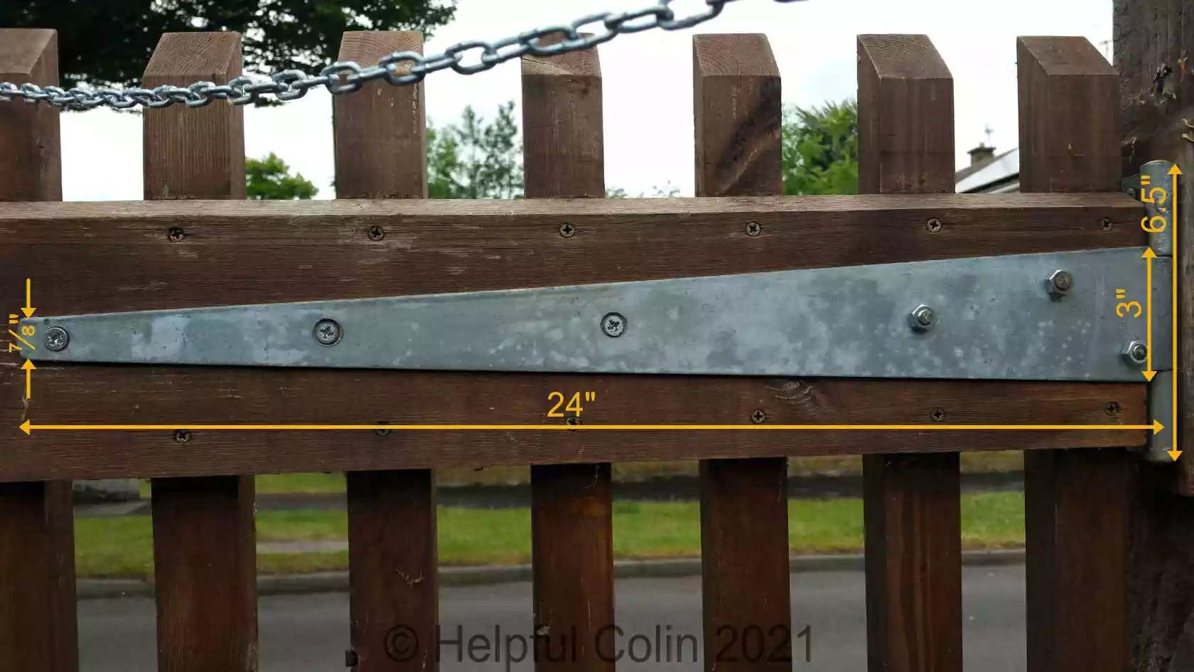
A heavy and sturdy see-through gate like this needs strong hinges, especially when people try to climb it. So I used two of these galvanised heavy duty beauties below. I don’t expect them to rust away anytime soon either.
An Unsatisfactory Hanging Method
There are two possible surfaces on the hinge post I could mount the hinges on. If I had used the one on the street side of the post and mounted the hinge normally (on the outside of the gate) it would have swung out into the street. That would be a danger to the public.
A Satisfactory Hanging Method
I pondered on various methods that didn’t seem to work before mounting the hinges on the other surface of the post as if they were butt hinges, i.e. between the end of the gate and the post. The screws cannot be removed while the gate is closed because the gate is in the way.
Mounting the hinges like this also allowed me to pad them out from the post at top and bottom. The padding thickness was adjusted to get the gate level and vertical and positioned within the 118cm passage width.
This method of mounting the hinges causes two situations:
- The top hinge requires long well threaded screws because the weight of the gate is trying to pull them straight out of the post.
- It puts the hinge strap on the inside of the gate against the rails (good), but with the countersunk holes of the strap facing the wood (bad).
Consequently I had to countersink the three screw holes at the end of the strap (which receive ordinary wood screws) from the opposite side to the existing countersinks. That wasn’t a problem – there was plenty of thickness to the metal for me to drill into. There is no zinc on the countersunk holes but the strap isn’t going too rusty as a result.
I used coach bolts, with their domed heads on the outside of the gate in the three holes near to the hinge pin. Their hinge holes don’t require countersinking since they have nuts on. The spacing works out well with two of them passing through slats without being too near the edge, while the third one just misses a slat.

Locking My Sturdy See-through Gate
What Form should The Lock Take
When I started building the gate I hadn’t settled on a method of locking it. I had to devise some form of locking mechanism, accessible from the inside of the passage. Neither myself nor my neighbour need to enter the property that way.
We usually use this gate when we put out our refuse bins to be emptied. So It doesn’t need to be unlocked from the street. We only need to unlock it, exit, return and lock it again from within.
A horizontal bolt and padlock would normally be the best method. However it would have to engage another neighbour’s fence which wasn’t in a good state at the time. I decided to see if I could latch it into the ground instead. The ground at this point is a strip of concrete at the end of a path of concrete slabs.
When I found that suitably long bolts were available, I decided I would lock the gate with a very long strong bolt 900mm (36″) long. This is the sort used on double gates. That’s where one gate is fixed to the ground by a bolt and the other locked to it.
The reason I chose a bolt this long is because the user doesn’t need to bend down to operate it.
Why Create A Leg?
Below is a photo of my Sturdy See-through Gate, without any waterproof preservative, spending a little time indoors while it rains outside. You can see that there’s no leg on slat №9 towards the bolt end. In retrospect I should have had one slat cut 10cm longer to accommodate a bolt.
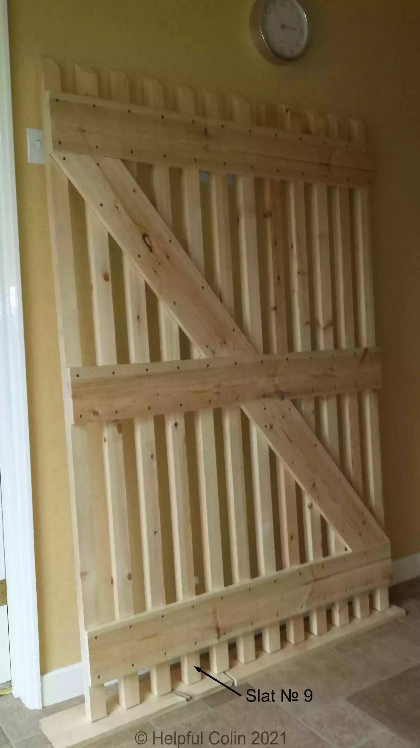
When I ordered the bolt I had only seen it in internet pictures and I hadn’t actually handled one like it either.
It was only after the bolt was delivered, when I could see its exact form, that I made decisions on how to mount it. It needed to be fixed to a flat surface together with the locking hasp & staple. Fortunately the slats were wide enough to accommodate the bolt guides.
In my opinion if I left the bolt exposed for 10cm near the ground it could get bent by a brute force attack. I also suspected the gate may need the added support of a leg if someone tried to climb over it.
Having realised I needed to lengthen a slat to make a leg for mounting a bolt guide nearer the ground. I also needed to pad out the slat, including its leg, to create a flat surface flush with the rails for the bolt guides to be mounted on.
Choosing The Best Slat To Mount The Bolt On
The position of the hole in the footpath slab determined which slat I attached it to. For the bolt to apply the best restraint for the gate, the bolt hole needed to be as far from the hinge as possible. If the path had been concreted for the full width of the passage I would probably have chosen to fit the bolt to slat №11.
As it is the path is made from slabs that are 3 feet wide with a narrow concrete strip 3 feet wide at the gate end. So I lengthened and padded out Slat № 9 to form a leg reaching down to the slab surface which is drilled to hold the bolt.
The leg has just a small amount of ground clearance allowing the gate to open normally. Any climber will weigh it down (about 5mm) until it touches the ground and supports their weight without damaging the gate.
How I Mounted The Bolt, Hasp & Staple
You can see in the picture below. The gate is laid out across the backs of two canvas covered garden seats. (The canvas was to protect the seats.) It was too large to work on when mounted on my workmates. This is My Alternative Bench mentioned earlier. The garden seats were set up with the tops of their backs parallel so that the gate could be assembled without being twisted.
Padding Out The Timber Behind The Bolt & Hasp
Below you can see the bolt padding being glued with Gorilla glue. It’s held while it sets by having the hasp staple and four bolt guides screwed in place. There was just one extra guide needed on rail R1.
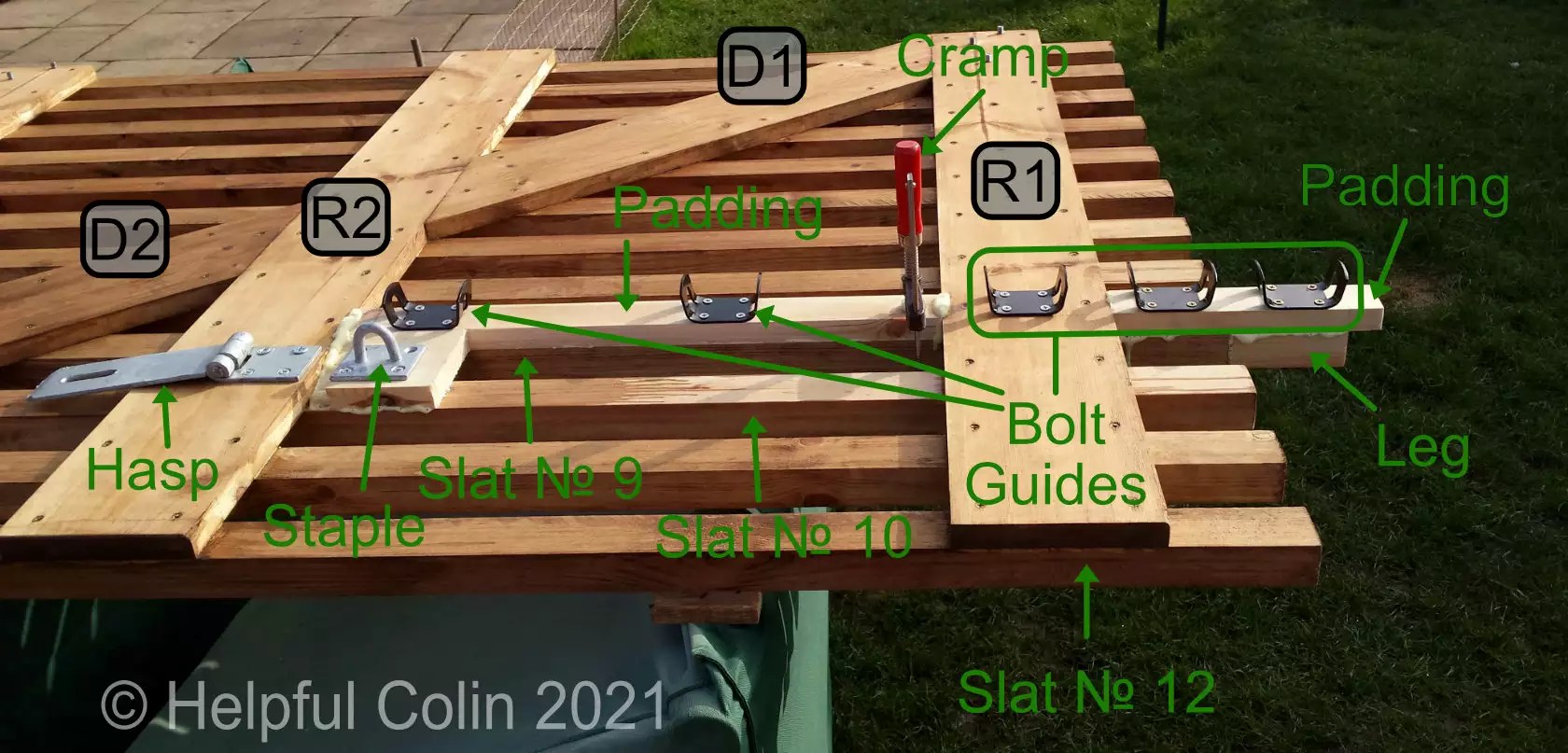
I also had to add 20mm timber to slats №9 & №10 to make them flush with the horizontal rails in order to support the bolt guides and associated padlock hasp’s staple. The top of the padding is cut away at an appropriate angle to allow the bolt handle to fit behind the flap of the hasp when it’s folded down. Locking the hasp with a padlock then prevents the bolt handle being lifted and so secures the gate.
The Leg Extension
The extra 10cm added to the leg was a slat off-cut 3.5cm × 4.5cm. I was careful to get the end attached to slat №9 very flat and square no all sides. I attached it with a 4″ × №12 countersunk screw. This was done by drilling a hole down the core of it to take the screw and enlarging the hole half way to take the head of the screw.
By this means the extension was screwed and glued onto the bottom of slat №9 with padding 2cm × 4.5cm × 23cm screwed and glued to the surface. I took advantage of two of the bolt’s guides screws to hold the padding in place. The padding was 3cm too long and was sawn to length once the glue had set. This has proved to be a strong leg so far.
Padding On Slat № 9 Between Rails
The padding between rails R1 and R2 is L shaped. For the lower part it is 4.5cm to match the slat. It widens out to span two slats №9 & №10 to facilitate the installation of the hasp’s staple. See pictures and diagrams. Again the padding is held by two bolt guides and their screws plus a cramp while the glue sets.
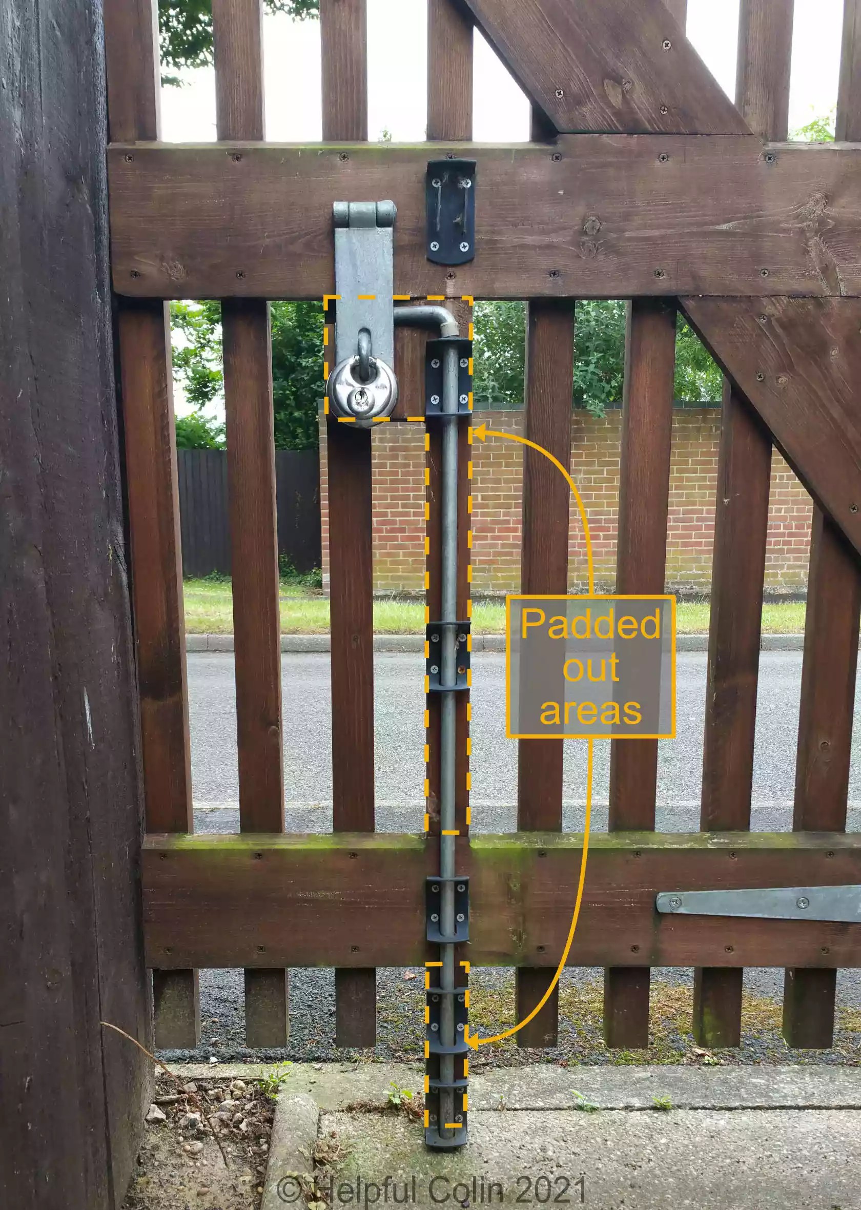
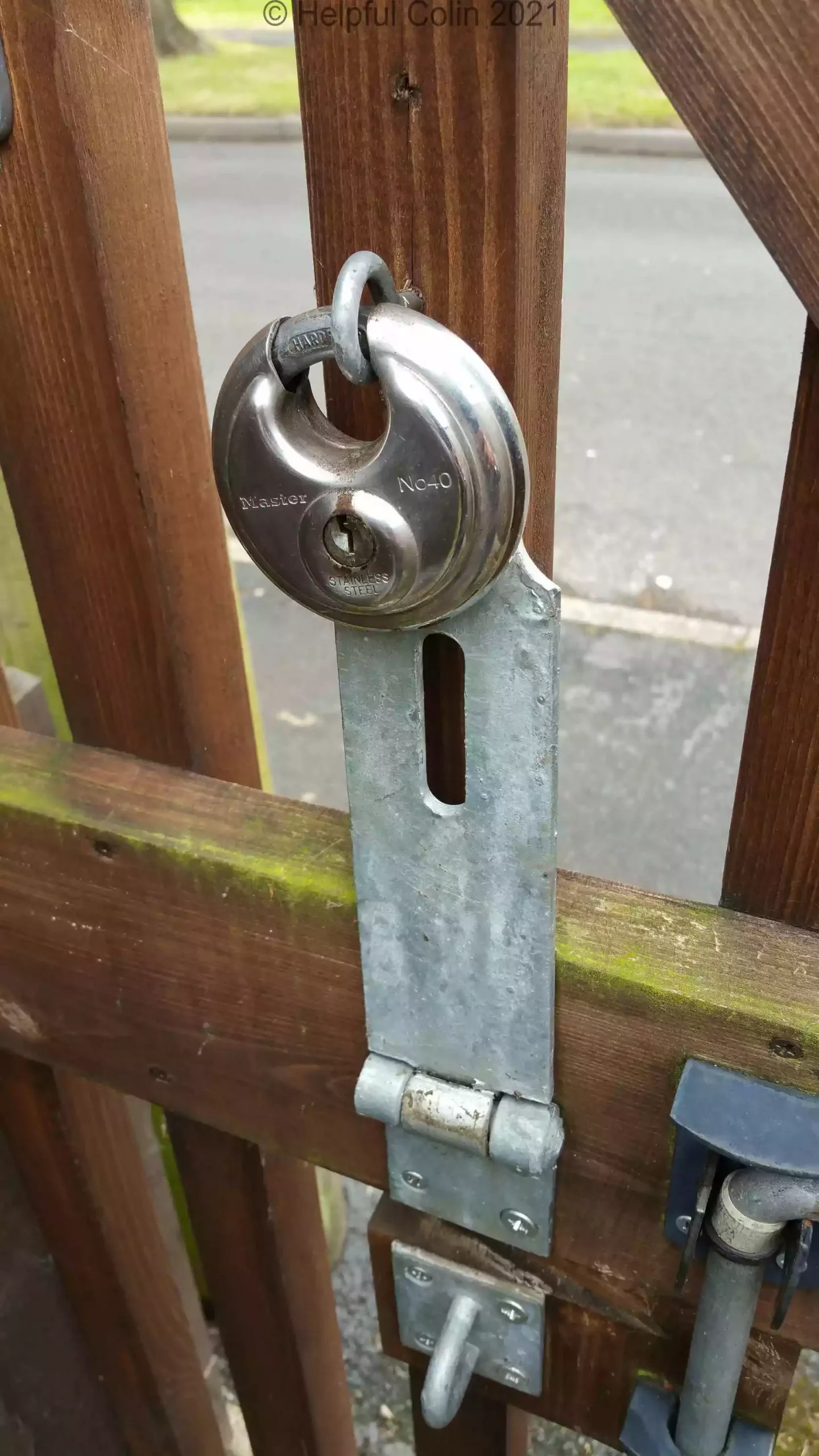
Below you can see where the padding is on the finished gate. You can also see the bolt down in the concrete and locked in place by the hasp, staple and padlock.
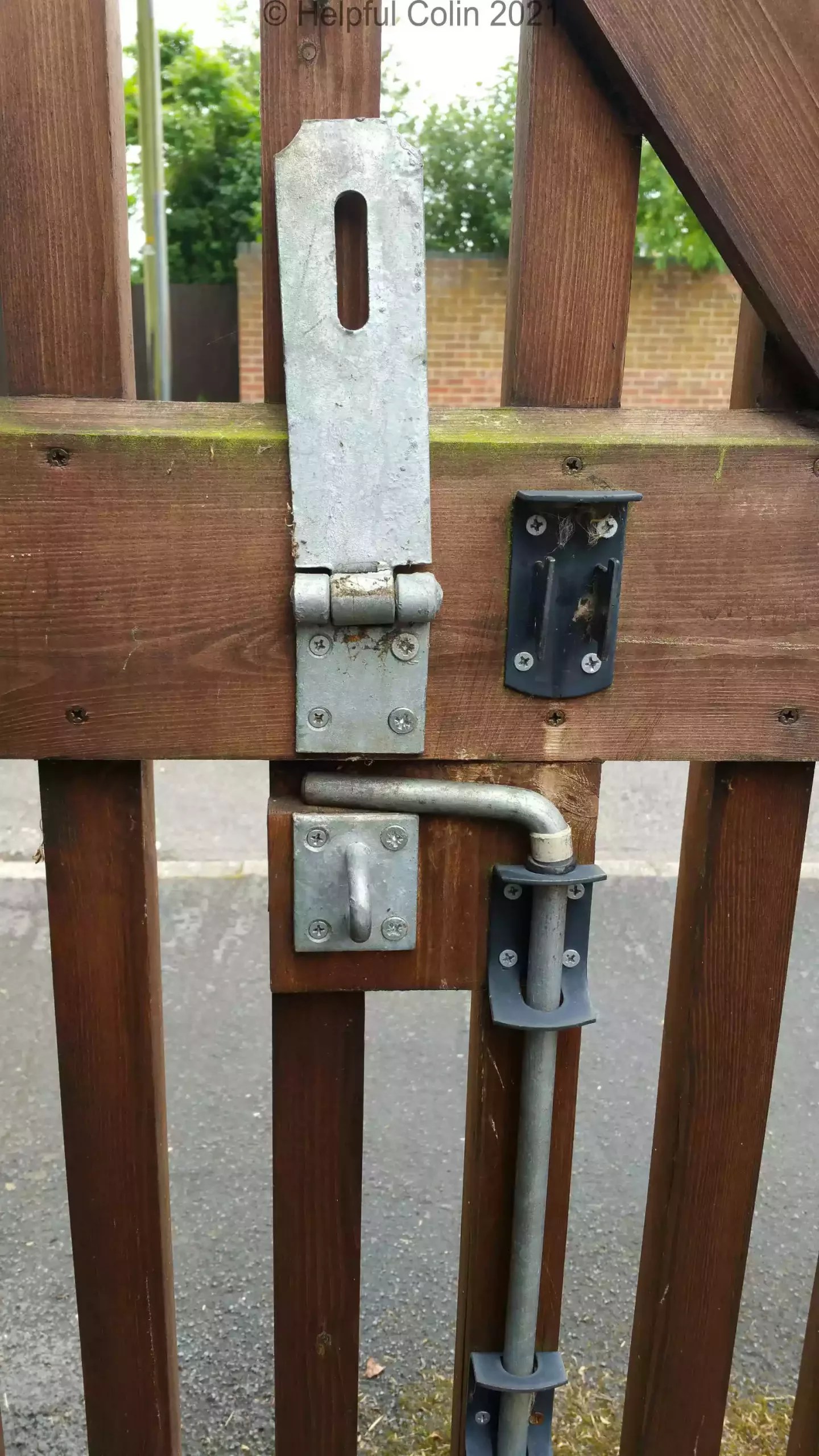
This picture below shows the cut away area for the bolt handle between the open hasp and the hasp’s staple.
Using A Disc Padlock
I have used them on my sheds because I think they are hard to cut open, don’t rust and can be easily warmed up and freed in frosty weather.
I chose to use a stainless steel disc padlock. Many other padlocks look OK, but have rustable coil springs to push the shackle open when the key releases it.
So there’s no corrosion and they are easy to thaw out in the winter, either by holding in the hand or by applying a hot damp cloth or by pouring boiling water over them.
The picture below shows the padlock in its “parking” eye. I mounted it too high and moved it down the gate so that the hanging padlock holds the open hasp up while the gate is moved about.
Holding The Gate Open
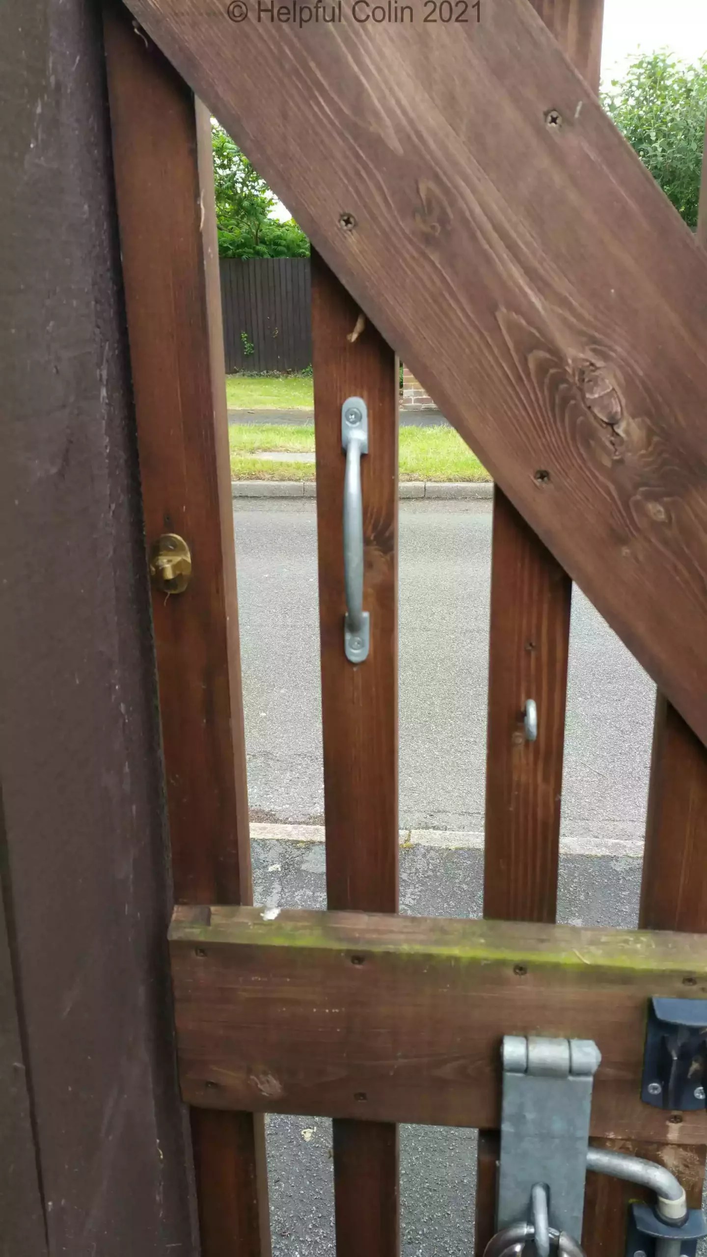
A gate like this one needs a hook to hold it open so that it doesn’t blow about in the wind. Because I need it to be held wide open and as flat as possible against my fence I had to get a short hook. The simple galvanised steel ones are often unsuitable because they are four or five inches long.
I got a lacquered brass one intended for boat cabins or indoor use. It came with a matching brass eye and I made sure it was fixed with real brass screws (not the ones sold with it). So not only does it look nice but because all components are brass it will be quite weather resistant.
Although the gate can be easily grasped by its slats to open and close it I provided a cheap aluminium handle. (Wood can offer splinters.)
The mounting points of these items on the rear of the gate can be seen below.
Restraining The Gate With A Safety Chain
The gate can swing into the street when unbolted if the wind catches it. So I have restrained it with a chain to prevent it:
- hitting a member of the public walking by,
- straining the hinges with its own momentum.
I’ve not provided a clapping strip, i.e. a strip of wood fixed to the adjacent fence to prevent it continuing beyond the closed position when it shuts. That’s because I didn’t want to attach anything to the neighbours fence.
Alternatively I could provide a stop on the ground for the gate leg to strike, but that would be a trip hazard.
My solution is a chain which becomes taut when the gate reaches the closed position. The chain has one end attached to the top of the gate and the other to my fence.
I attached each end of the chain to a substantial eye made for screwing directly into wood. I had to open up each eye to slip the chain on and close it again using a bench vice. I’ve found the best way to do this is to clamp the screw part in the vice and twist the eye right or left with pliers. Then slip the last link of the chain on loop and twist the eye the opposite way to close it again.
Doing it by opening the eye to a larger diameter is more difficult and damaging. It just removes a lot of plating or paint from the eye.
Method of Mounting The Chain On Fence & Gate
To put the chain in place without any twists left in it from screwing the eyes into the wood:
- Just screw one end’s eye into the wood and count how many turns it takes to get it in.
- Get the chain straight, then twist it as if unscrewing the unattached 2nd eye by as many turns to put twists in it.
- With those twists still in the chain, screw the 2nd eye into the wood with the same number of turns and the previously made twists will disappear.
The chain’s zinc plated, welded, oval, links each have an inside measurement of 14-15mm.
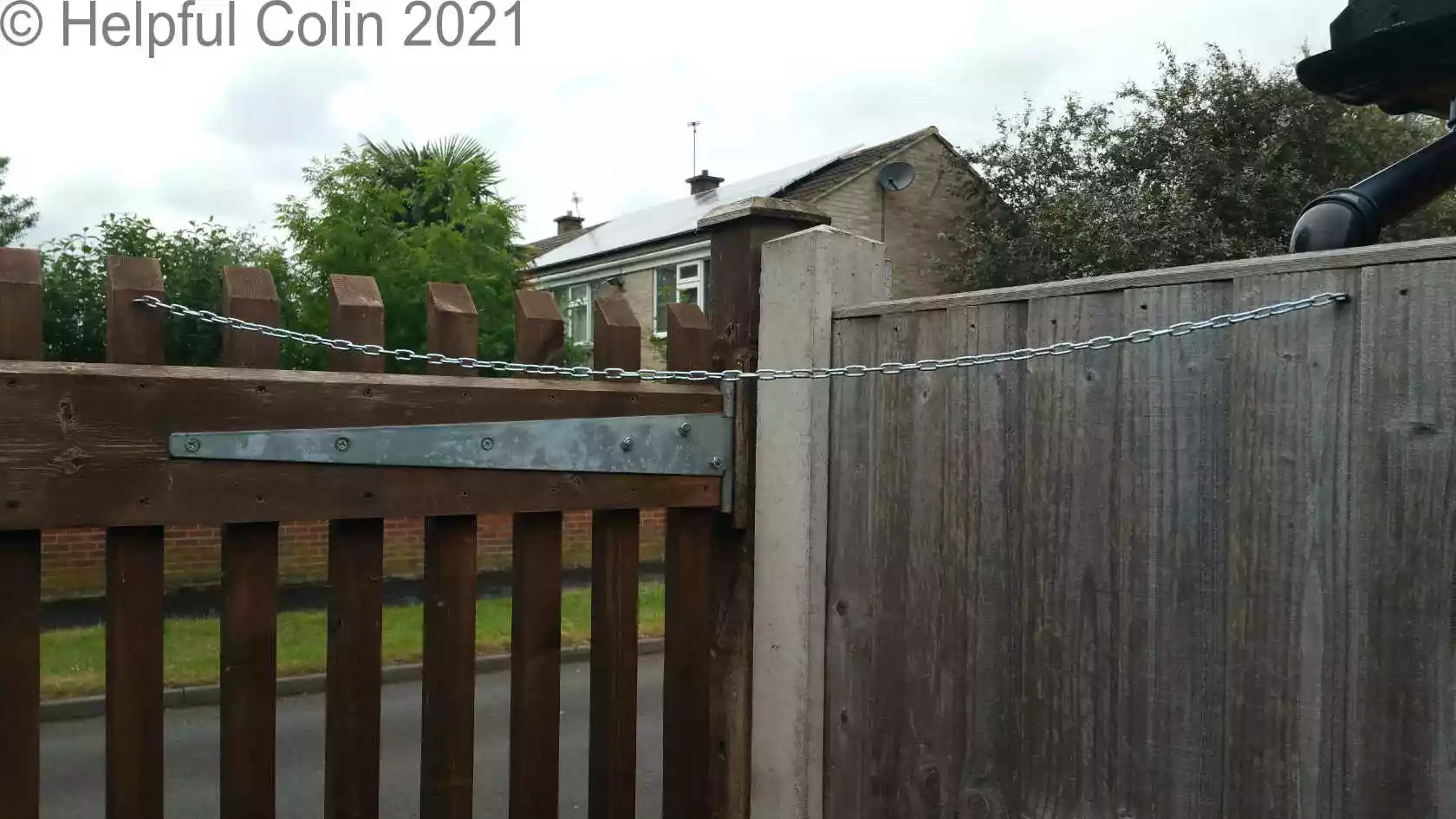
Initially I used synthetic cord. It took the tension OK until sunlight rotted it (after a year), so I replaced it with the chain.
Can The Gate Resist Forced Entry?
Two hinges and the bolt in the ground hold the gate in place. Anyone trying to force it open may attempt to push or pull it at the top corner above the bolt.
Below the twisted gate shows 11° of movement. That’s more than the gate has ever had as far as I’m aware.
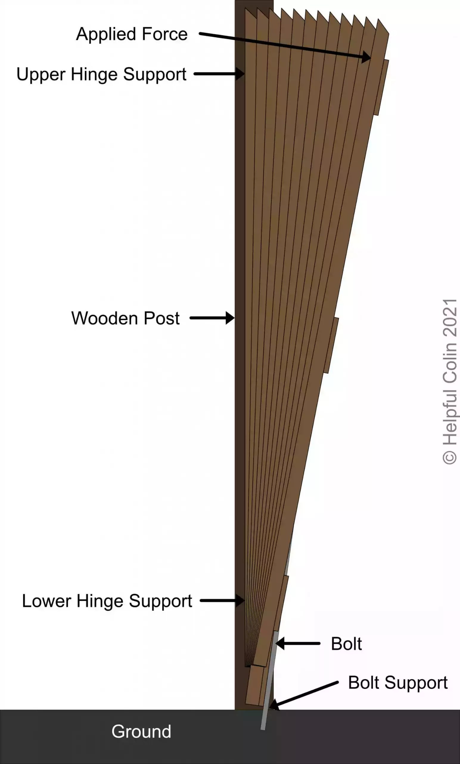
Manually applying forces to the gate has shown it to be very strong. Someone standing on the ground cannot apply such force when they reach up to the top corner of the gate. If they push on the gate lower down they can’t get the necessary leverage. They would have to attack it in a violent and noisy way to break it down.
Applying Preservative To The Timber
I made this gate of untreated pine. So I had to paint it with preservative after construction. If I made another gate I would consider using tanalised timber for it.
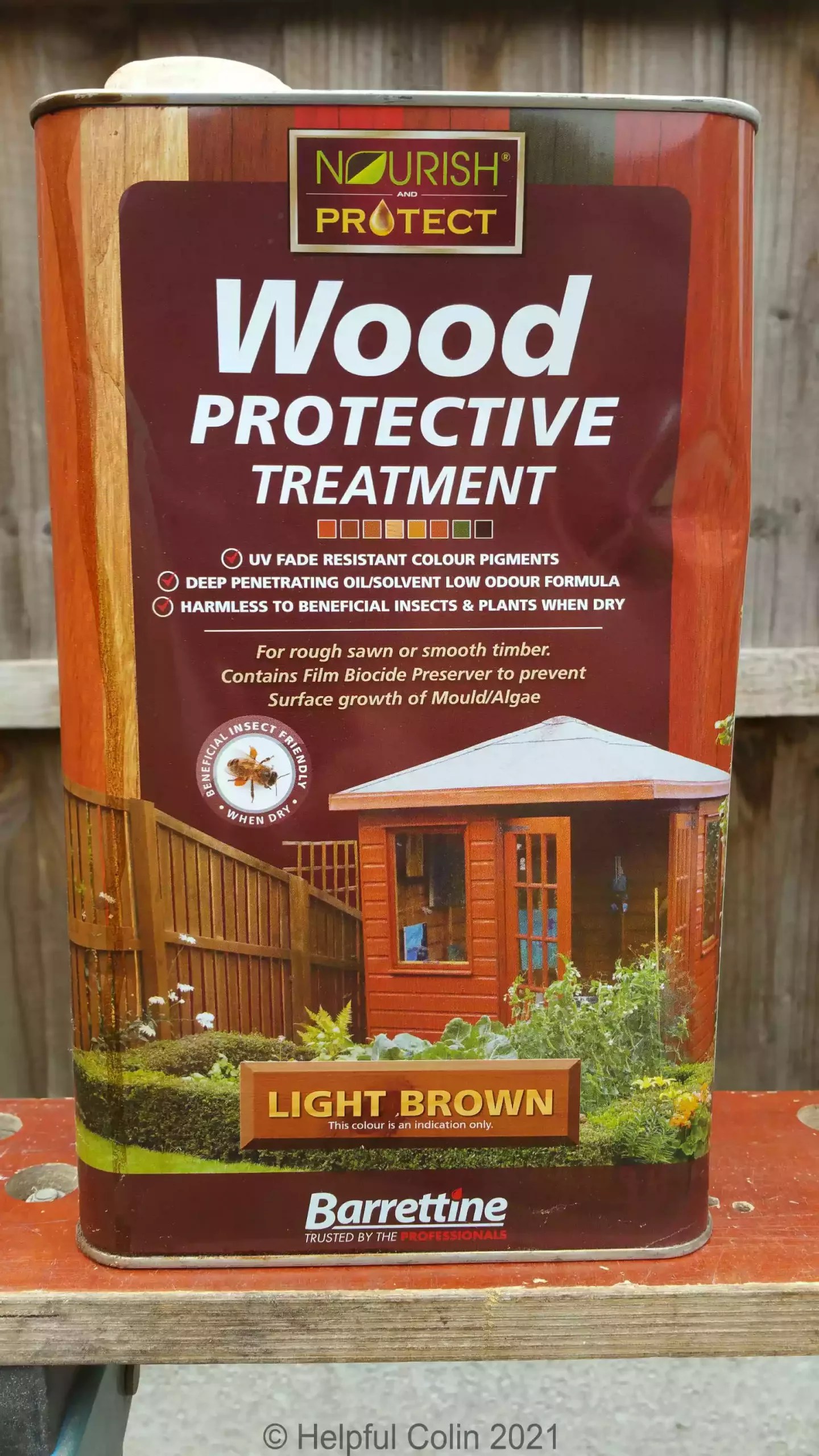
I used Barrettine Wood Protective Treatment, Light brown in colour.
I prefer spirit based preservative. Rain doesn’t wash it off unlike water based preservative. Two coats is a good starting point. I painted it five years ago and now I’ve just given it another coat. You can see the gate below with just one coat on.


Footnotes
1. Furniture = The hardware such as hinges, bolts, handles, etc., attached to the woodwork. See this comprehensive list.
2. PAR = Planed All Round. Wood planed on all sides to make it smooth.
Leave a Reply