silent fill valve

How A Toilet Cistern Silent Fill Valve Works

Introduction

This article is in effect an addendum to the post Repairing A Toilet Silent Fill Valve which explains how to access and dismantle such a valve and inspect or change the diaphragm that sits in the valve. That post also explains what is, and is not, silent about a Silent Fill Valve. This is now complemented by the post Replacing A Toilet Fill Valve.

In order to satisfy the requirements of Internet SEO (Search Engine Optimisation) the valve is referred to, in this article, specifically as a Toilet Silent Fill Valve or more generally Silent Fill Valve but its full title is a Silent Fill Toilet Cistern Inlet Valve since it is:

  1. A Valve.
  2. An Inlet Valve.
  3. A Cistern Inlet Valve.
  4. A Toilet Cistern Inlet Valve.
  5. A Silent Fill Toilet Cistern Inlet Valve.

This type of valve is complex and deploys a built-in mechanism which uses the inherent water pressure in the Mains Water to drive the valve from the closed to open position and then from the open to closed position. The mechanism is controlled by a much smaller valve in the form of a stopper covering a pinhole which requires a much smaller effort to operate it than the main valve.

The article endeavours to explain to the reader how the complete valve works so that they understand the order in which physical processes take place and why they follow on from each other as they do. The theory behind the workings of the valve are developed from the basic principles of forces and pressures acting on the individual parts but without the detail of too many mathematical formulae.

Basics About The Valve

silent fil valve
Example similar to mine but this hasn’t got a screw cap.

The Silent Fill Valve described here is mounted on a support tube moulded so that it can be mounted in the bottom of a cistern (usually a porcelain toilet cistern about 1cm thick) where the water feed comes from below.

The screw thread moulded on the end of the support tube is ½” BSP (British Standard Pipe), the same as that on a standard ½” (15mm) tap connector.

The support tube fits through a conical rubber washer then the hole in the bottom of the cistern and is fixed with a plastic nut and washer. Then a ½” (15mm) tap connector, often flexible these days, can be connected to it from a water supply underneath the cistern where the pipes are out of sight.

NOTE: The rubber washer should be on the inside of the cistern with the cone shape pressing into the hole and the ridge on the nut should go into the hole from the outside to keep it centred.

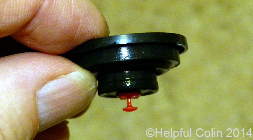
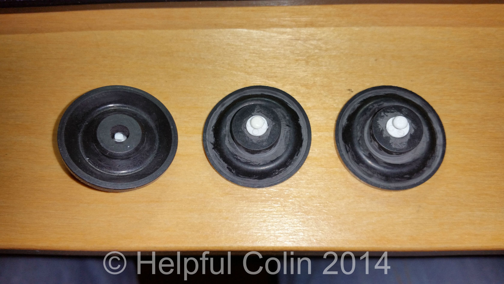
The valve has one internal moving part – the Diaphragm which moves up to open the valve and down to close it.

Externally the moving parts consist of a rocking Arm driven by an attached Float (blue in this picture) which can be adjusted to determine the height of water in the Cistern. These two parts open and close a small pinhole valve to control the actions of the Diaphragm.

The anti-syphoning collapsible output pipe can be seen dangling in front of the float in this picture of a later version which is similar to the one described here. It has a rigid plastic support inside it to keep it in position. Else air in it would cause it to float on top of the water and then the water flowing through it would spray in all directions.

The Advantages A Diaphragm Silent Fill Valve Has Over A Ballcock

Ballcocks (float valves) can be very basic – a brass piston with a rubber bung on the end connected by a brass lever to a rising spherical float slowly closes the hole at the end of a pipe until no more water can get through the pipe. The water initially flows fast but as the float rises the flow of water is restricted and so the float rises ever more slowly. The restriction reduces ever more slowly as a consequence. So the rate at which the cistern fills goes down and down. Who knows it might never get to the fill line and just drip into the cistern for ever.

silent fill valve
Ballcock or Float Valve without a float. (Viewed looking up at it.)

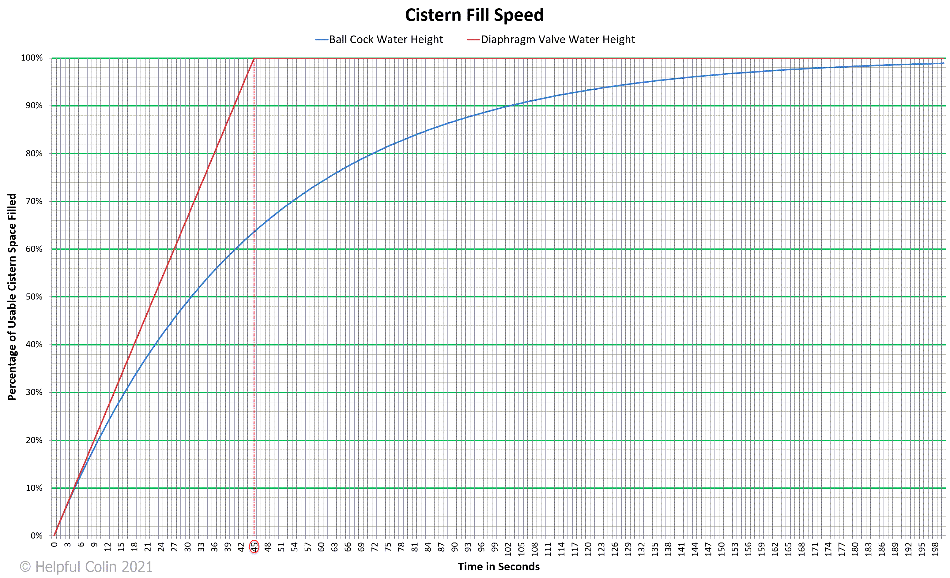
People want a cistern to fill quickly so it can be flushed (emptied) again soon. In less than one minute perhaps. I’ve timed my silent fill valve cistern and it fills in about 30 seconds after a short flush and 45 seconds after a long flush. How does it do that? Well it stays full open for most of the time and then completely shuts off the flow of water rapidly but not too quickly, since there is no banging in the pipes (a sign of a very rapid shut off). How? By using mains water pressure to rapidly move the diaphragm and close the valve as soon as it starts closing. This short fill time helps it to be a silent fill valve because after 30 to 45 seconds there is no more noise. With a ball cock the filling sound can sometimes go on for several minutes.

Below is an assumed Cistern Fill Speed graph comparing fill speeds of a ball cock, taking around 180 to 200 seconds to fill, with the diaphragm of a silent fill valve taking only 45 seconds to fill, after a long flush, when the initial (maximum) flow rates are the same at (2.2%)/s (see enlarged graph, by selecting the image, to get more detail):

Cistern Fill Speed Graph
Select the graph to enlarge it.

The Fill Cycle Explained

The explanation here describes an Ideal Standard Silent Fill Valve mounted in a toilet cistern.

The four stages of the Fill Cycle depicted here:

  1. The Static State – where the Silent Fill Valve is closed, the Cistern is full and Cistern Water is in a static state (neither filling nor emptying);
  2. The Fill Cycle Starts – when the Silent Fill Valve opens during flushing;
  3. The Silent Fill Valve Begins Closing – when the Cistern is nearly full and the Top Cover Pinhole is closed;
  4. The Fill Cycle Ends – when the Cistern is full and the Silent Fill Valve closes.

Key to water colours used in Figs. 1 to 4 below where the water is coloured according to its pressure:

  • Water at Mains Pressure.
  • Water at Cistern Pressure, i.e. at or near atmospheric pressure.
  • Water pressure dropping from Mains Pressure down to Cistern Pressure.
  • Water pressure rising from Cistern Pressure up to Mains Pressure.

NOTE: The Diaphragm, Diaphragm Support and Pinhole Cone are drawn in simplified form in Figs. 1 to 4. Refer to ‘The Diaphragm In Detail’ to see enlarged more realistic diagrams.

This description begins with the cistern in a static state, i.e. no water is flowing in or out of the cistern. The water supply is turned on and the full cistern is waiting to be flushed (emptied).

1. The Static State

Refer to Fig. 1.

Fig. 1 – Silent Fill Valve Closed, Cistern Full & Water Static.

Silent Fill Valve Closed, Cistern Full & Water Static.

A labelled diagram of a section through the closed Silent Fill Valve. It’s closed by the Diaphragm sealing off the Mains Water at the top of the Silent Fill Valve Support Tube. The Cistern is filled with water up to the Fill Line and no water is flowing anywhere.

The force keeping the Silent Fill Valve closed is generated by a mechanism, within the valve, which is activated when water escaping through a pinhole in the valve is stopped. The pinhole is closed by the upward force of the Float’s buoyancy forcing a rubber stopper down onto the Top Cover Pinhole Cone.

The dark red arrows in the diagram show the direction of static forces and pressures acting on various parts thus:

  • The Float is buoyant in the full Cistern and pushing upward against the Adjusting Screw.
  • The Adjusting Screw is pushing up on one end of the Arm.
  • The other end of the Arm is levering the Rubber Stopper down onto the Top Cover Pinhole Cone and keeping the pinhole closed.
  • The Diaphragm is held down, by the pressure difference across it, keeping the valve closed.

The state of the Cistern Water and Silent Fill Valve in detail is:

  • The water level is up to the Fill Line.
  • The Float is buoyant in the water and applying an upward force to the Float end of the Arm via the adjusting screw.
  • The Arm can rock as required on the Fulcrum Pivot so that the other end, containing the rubber stopper, bears down on the Top Cover Pinhole Cone. This stops water coming out of the pinhole under mains pressure.
  • The cross-sectional area of the pinhole is so small that the small float, with leverage from the arm, can easily apply the necessary force to counter the mains pressure.
  • The 1mm hole in the Diaphragm Grommet, although restricted by a plastic pin, allows the water pressure above to rise until it equals the mains pressure from the Support Tube below. (The Pin in the Diaphragm hole may drop down.)
  • The Diaphragm is in a relaxed position, holding the natural shape it is moulded to, and all of it is under mains pressure from above which presses the centre of the Diaphragm down onto the Support Tube. In this position it cuts off the Mains Water so it cannot pass from Inlet to Outlet.
  • The water in the Outlet Pipe is at Cistern Pressure (approximately atmospheric pressure) because it is cut off from the main supply by the closed diaphragm but is connected to the water in the cistern via the Outlet Pipe. This low Cistern Pressure extends all around the red annular Diaphragm Support underneath the Diaphragm, even though there is not much of a gap.
  • It’s the pressure difference between both sides of the Diaphragm (high above, low below), in the area of the red annular Diaphragm Support, that keeps the Diaphragm forced down to shut off the Mains Water going to the Cistern.
  • The centre thick rubber area has the same pressure on both sides (Mains Pressure) so the forces in that area are neutralised.

NOTE: Only the surface of the water in the Cistern is at atmospheric pressure. Water below the surface is above atmospheric pressure due to the weight of water above. The water in the Outlet Pipe above the Cistern Water has reduced pressure according to its height above the Cistern Water surface. That water is trying to fall out of the Outlet Pipe due to gravity but is supported by atmospheric pressure acting on the cistern water while air cannot get into the Outlet Pipe. Remember Atmospheric Pressure can lift a column of water 10.3m (33.8 feet).

2. The Fill Cycle Starts

Refer to Fig. 2.

Fig. 2 – Silent Fill Valve Opens During Flushing (Cistern Emptying).

Silent Fill Valve Opens During Flushing (Cistern Emptying)

A labelled diagram of a section through the open Silent Fill Valve with water flowing from Inlet to Outlet.

In this state the Cistern has just been flushed and the water level is dropping rapidly. The falling Float has tilted the Arm and lifted the Stopper off the Top Cover Pinhole Cone allowing water to escape through the pinhole. The escaping water has allowed the pressure above the Diaphragm to drop. The mains Pressure below the Diaphragm has then pushed it up and opened the valve rapidly. Mains Water is rushing through the valve to the Outlet Pipe where it can fill the cistern.

helpfulcolin.com

NOTE: It has been pointed out by Bob Jenson (who commented on 26/02/2022) that the flow rate through the pinhole in the cone appears to be greater than the flow rate around the pin in the red grommet, due to there relative sizes. He suggests that this keeps the pressure above the diaphragm low when the pinhole is open because water can escape faster than it can be replenished through the restricted hole in the grommet.

The green arrows in the diagram show the direction of movement of water and various parts thus:

  • The Cistern Water level falls.
  • The Float drops maintaining its buoyancy until it hangs from the adjusting screw.
  • The Arm rocks to the open position.
  • The rubber Stopper in the Arm goes up to open the pinhole.
  • Water goes up through the pinhole in the Top Cover Pinhole Cone.
  • The Pin in the Diaphragm hole may be pushed up.
  • The Diaphragm goes up opening the valve.
  • Water rushes through the Silent Fill Valve Support Tube as it flows from Inlet to Outlet and into the Cistern.

The state of the Cistern Water and Silent Fill Valve in detail is:

  • The water level is falling rapidly as the Cistern discharges into the toilet.
  • The Float is no longer buoyant and is suspended on its Adjusting Screw which is hanging from the Arm tilted by the weight of the Float.
  • Tilting the Arm has lifted the Rubber Stopper off the Top Cover Pinhole Cone so that water can escape from above the Diaphragm through the pinhole.
  • The Diaphragm is pushed up under mains pressure as the water above the Diaphragm escapes.
  • Once the Diaphragm has begun to lift, mains pressure from the inlet tube pushes water into the Outlet Pipe chamber from where it can get between the Diaphragm and its support adding to the area of the Diaphragm being forced upward so it opens quickly. This is the mechanism at work opening the valve.
  • Water continues to flow from the Inlet to the Outlet  until the end of the fill cycle.
  • During the fill cycle water continues to escape out of the pinhole via the restricted Diaphragm hole.

3. The Silent Fill Valve Begins Closing

Refer to Fig. 3.

Fig. 3 – Silent Fill Valve Starts Closing Near The End of A Fill Cycle.

Silent Fill Valve Starts Closing Near The End Of A Fill Cycle

A labelled diagram of a section through the Silent Fill Valve after it has started closing and the Cistern is nearly full of water.

In this state the Cistern has been filling for some time and the water level has risen. In the later stages the Float has become buoyant again and applied an upward force to the Arm and pressed the Rubber Stopper down on the Top Cover Pinhole Cone shutting off the flow of water through the pinhole and commencing the closure of the Silent Fill Valve. The Diaphragm starts to press down and Mains Water flow into the Cistern decreases.

The dark red arrows in the diagram show the direction of static forces acting on various parts thus:

  • The Float is buoyant and pushing upward against the Adjusting Screw.
  • The Adjusting Screw is pushing up on one end of the Arm and rocks it to the closed position.
  • The other end of the Arm pushes the Rubber Stopper down onto the Top Cover Pinhole Cone to close the pinhole.

The green arrows in the diagram show the direction of dynamic movement of water and various parts thus:

  • The Cistern Water level continues rising.
  • The Pin in the Diaphragm hole may continue to be dragged up by the water flowing through the hole.
  • The Diaphragm goes down due to the increase in pressure above it and a drop in pressure below it.
  • Water in the Silent Fill Valve Support Tube slows down as it flows from Inlet to Outlet.

The state of the Cistern Water and Silent Fill Valve in detail is:

  • The water level is nearly up to the Fill Line. (Observe THE GAP between the water and the Fill Line in the diagram.)
  • Water still passes through the Silent Fill Valve while the Diaphragm is partly open.
  • The Diaphragm closes slowly as the mains pressure builds on the top side of it by leaking through the restricted hole in the Grommet. This is the mechanism at work closing the valve.
  • The natural compliance of the Diaphragm forces the centre down as the difference in water pressure above (high pressure) and below (low pressure) allows it.
  • As the Diaphragm closes the water flow from Inlet to Outlet diminishes and the Outlet Pipe pressure falls. This same low pressure region is connected to the underside of the Diaphragm above the red annular Diaphragm Support and a pressure difference builds up between the top and bottom surfaces of the Diaphragm (high above, low beneath). This helps to force the Diaphragm down until it rests on top of the Inlet Tube and red annular Diaphragm Support. Then it completely stops the water flow from Inlet to Outlet thus closing the Silent Fill Valve.

These two things (listed below) work together to slowly close the Silent Fill Valve without any hammering in the pipework of the building:

  1. Slow build up of pressure above the Diaphragm as it rises towards mains pressure.
  2. Slow reduction of pressure at the Outlet Pipe and in the associated chamber within the Silent Fill Valve Body causing slow reduction of pressure under the Diaphragm above the red annular Diaphragm Support.

4. The Fill Cycle Ends

Refer to Fig. 4.

Fig. 4 – The Cistern Is Full & The Silent Fill Valve Closes.

The Cistern Is Full & The Silent Fill Valve Closes

A labelled diagram of a section through the Silent Fill Valve after it has just closed with the Cistern full of water again.

In this state the Cistern has been filling for some time, the water level has risen to the Fill Line. The Silent Fill Valve is closed as the Diaphragm has pressed all the way down onto the Silent Fill Valve Support Tube and has stopped the Mains Water from over filling the Cistern. A small amount of water squeezes through the restricted hole in the Diaphragm Grommet until the pressure above it has risen to mains pressure.

The dark red arrows in the diagram show the direction of static forces acting on various parts thus:

  • The Float is buoyant and pushing upward against the Adjusting Screw.
  • The Adjusting Screw is pushing up on one end of the Arm.
  • The other end of the Arm is levering the Rubber Stopper down onto the Top Cover Pinhole Cone and keeping the pinhole closed.
  • The Diaphragm is held down, by the pressure difference across it, keeping the valve closed.

The green arrows in the diagram show the direction of movement of water and various parts thus:

  • The last drop of water goes up the Support Tube to raise the pressure above the Diaphragm to mains pressure.
  • The Diaphragm beds down onto its support due to the increase in pressure above and decrease below it.

The state of the Cistern Water and Silent Fill Valve in detail is:

  • The water level is up to the Fill Line. (Observe NO GAP between the water and the Fill Line in the diagram.)
  • The Float is buoyant in the water and applying an upward force to the Float End of the Arm via the adjusting screw.
  • The Arm can rock as required on the Fulcrum Pivot so that the other end, containing the rubber stopper, bears down on the Top Cover Pinhole Cone. This stops water coming out of the pinhole under mains pressure.
  • The cross-sectional area of the pinhole is so small that the small float, with leverage from the arm, can easily apply the necessary force to counter the mains pressure.
  • The 1mm hole in the Diaphragm Grommet, although restricted by a plastic pin, allows the water pressure above to rise until it equals the mains pressure from the Support Tube below. (The Pin in the Diaphragm hole may drop down.)
  • The Diaphragm is in a relaxed position, holding the natural shape it is moulded to, and all of it is under mains pressure from above which presses the centre of the Diaphragm down onto the Support Tube. In this position it cuts off the Mains Water so it cannot pass from Inlet to Outlet.
  • The water in the Outlet Pipe drops to Cistern Pressure (approximately atmospheric pressure) because it is cut off from the mains supply by the closed diaphragm but is connected to the water in the cistern via the Outlet Pipe. This low Cistern Pressure extends all around the red annular Diaphragm Support underneath the Diaphragm, even though there is not much of a gap.
  • It’s the pressure difference between both sides of the diaphragm, in the area of the red support (395mm2) plus the downward pressure on the thick rubber area resting on the Support Tube (32mm2), that keeps the diaphragm forced down to shut off the Mains Water going to the cistern.
  • The centre thick rubber area in contact with the water inside the Support Tube has the same pressure on both sides (Mains Pressure) so the forces in that area (63mm2) are neutralised.

The Silent Fill Valve Diaphragm In Detail

The diaphragm and its housing work as a valve due to some very fine holes and gaps that allow the water pressure to equalise on both sides of the diaphragm but don’t allow water to pass through quickly. The diagrams below (Fig. 5 and Fig. 6) of the Silent Fill Valve Diaphragm show an enlarged cross-section of the valve with the important working parts to a scale of approximately 3:1 on a 94 dots per inch PC monitor. It’s only at this scale that the fine holes and gaps, through which the water passes, and the shapes of the parts can be seen.

Key to water colours used in Figs. 5 & 6 below where the water is coloured according to its pressure:

  • Water at Mains Pressure.
  • Water at Cistern Pressure, i.e. at or near atmospheric pressure.
  • Water pressure between Mains Pressure and Cistern Pressure.

1. Silent Fill Valve Closed – A Static State

Refer to Fig. 5 and Fig. 6.

Fig. 5 – Silent Fill Valve Diaphragm In The Closed Position.

Silent Fill Valve Diaphragm In The Closed Position
Fig. 5 – Select this image to enlarge it.

Fig. 5, above, shows a section through the Silent Fill Valve Diaphragm in The Closed Position. This is the state depicted in section ‘1. The Static State’ and section ‘4. The Fill Cycle Ends’ in ‘The Fill Cycle Explained’ above.

Waters at A and B are at mains pressure. The Rubber Stopper, forced down by the Arm, is preventing water escaping through a pinhole in the Pinhole Cone on the Top Cover. The cone shape containing the pinhole allows it to dig into the Rubber Stopper and make a good seal.

Water at B is connected to A through the restricted hole in the Red Grommet, mounted in the centre of the Diaphragm, allowing the static pressure of these two volumes to equalize.

Water at C is at a low pressure because it is trying to fall out of the Outlet Pipe and into the cistern due to gravity. The Red Annular Plastic Diaphragm Support is not sealed against the central bulge of the Diaphragm so the pressure at C extends all the way under the Diaphragm to the point where it is clamped to the valve body.

This difference in static pressure between B and C keeps the valve shut so that water cannot travel from A to C and into the cistern.

The effective area of downward pressure at B is the area above C  = 395mm2 (see ‘4. Calculation of The Silent Fill Valve Diaphragm Areas’).

The Dynamics of Lowering The Diaphragm

This is the state depicted in section ‘3. The Silent Fill Valve Begins Closing’ in ‘The Fill Cycle Explained’ above.

Once the pinhole in the Top Cover Pinhole Cone is closed and water can no longer escape from B  to D in Fig. 6. The pressure at B begins to build up to mains pressure. Then as the difference in pressure between (A + C + T) and B diminishes the natural compliance of the Diaphragm forces its centre down onto the top of the Support Tube.

While the Diaphragm is moving down the flow from A to C is reduced and the pressure at C, which extends under the Diaphragm Support, starts to fall increasing the downward force.

When the Diaphragm arrives on top of the Support Tube water at A is cut off from C and the pressure at C drops to Cistern Pressure. The area under the Diaphragm A + C + T (490mm2), which was subject to mains pressure is reduced to Area A (63mm2), but the area with a differential (and downward) force applied is Area C (395mm2) (see ‘4. Calculation of The Silent Fill Valve Diaphragm Areas’). Arguably Area T (32mm2) also has a downward force acting on it once the diaphragm is closed and that part of it rests on the Support Tube. The difference in pressure between the top of the Diaphragm and the bottom is then at its maximum and the Diaphragm is forced down by this mechanism.

2. Silent Fill Valve Open – A Dynamic State

Refer to Fig. 6 and Fig. 7.

Fig. 6 – Silent Fill Valve Diaphragm In The Open Position.

Silent Fill Valve Diaphragm In The Open Position
Fig. 6 – Select this image to enlarge it.

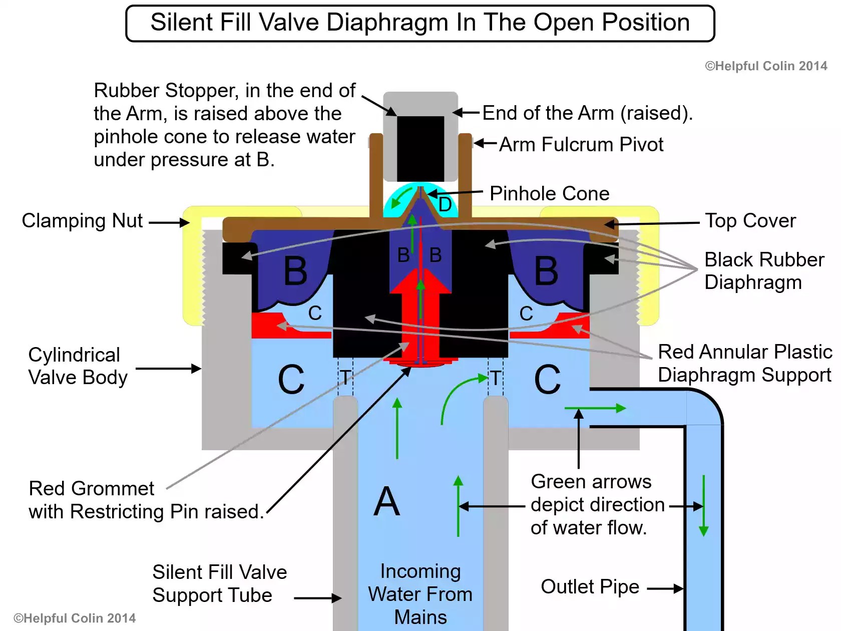
Fig. 6, above, shows a section through the Silent Fill Valve Diaphragm in The Open Position. This is the state depicted in sections ‘2. The Fill Cycle Starts’ in ‘The Fill Cycle Explained’ above.

The Rubber Stopper has been lifted off the Top Cover Pinhole Cone by the tilting Arm and water B above the Diaphragm is escaping under pressure (between mains and atmospheric) to D where it drains into the cistern.

The pressure difference between waters (A + C) and B lifts the Diaphragm. Once lifted the area under the diaphragm increases to include T. The lifting pressure difference operating on the diaphragm then becomes that between waters (A + C + T) and B. While there is this pressure difference the valve stays open so water flows from A through T & C to the Outlet Pipe and into the cistern.

NOTE: The area under the diaphragm (A + C + T) = the area above the diaphragm B until the diaphragm is forced up against the Top Cover. Once it seals against the Top Cover the effective area of B is temporarily reduced to the area above the Red Grommet.

The Dynamics of Raising The Diaphragm

Although water at B is slowly replaced by water from A under mains pressure, through the restricted Diaphragm Grommet hole, B is not at mains pressure once it becomes dynamic because it can escape through the Top Cover Pinhole Cone faster than it can be replaced. So the pressure difference between water at A and B lifts the Diaphragm initially.

helpfulcolin.com

NOTE: It has been pointed out by Bob Jenson (who commented on 26/02/2022) that the flow rate through the pinhole in the cone appears to be greater than the flow rate around the pin in the red grommet, due to there relative sizes. He suggests that this keeps the pressure above the diaphragm low when the pinhole is open because water can escape faster than it can be replenished through the restricted hole in the grommet.

Waters at A and C become directly connected when the Diaphragm is lifted initially and the effective lifting area increases from 63mm2 (Area A) to 490mm2 (Area A + Area C + Area T). This is equal to Area B. (see 4. Calculation of The Silent Fill Valve Diaphragm Areas) so water at C begins to rise towards mains pressure. The Red Annular Plastic Diaphragm Support is not sealed against the central bulge of the Diaphragm so the pressure at C extends all the way under the Diaphragm to the point where it is clamped to the valve body.

The increased area upon which the mains pressure acts as the Diaphragm lifts speeds up its lifting. That is the mechanism at work.

The Restricting Pin in The Red Grommet

When fully inserted (raised in Fig. 6) the head of the Restricting Pin doesn’t seal the hole in the Diaphragm Grommet because it is spaced away by four circular studs moulded onto the grommet allowing water to pass (see Fig. 7 which shows the Silent Fill Valve Diaphragm correctly oriented). The Restricting Pin serves to limit the flow through the grommet hole.

3. Silent Fill Valve Diaphragm Grommet Detail

Refer to Fig. 7.

Fig. 7 – Diaphragm Grommet Detail.

diaphragm shown in its working attitude
Fig. 7 – The Diaphragm shown in its operational attitude. (Select this image to enlarge it.)

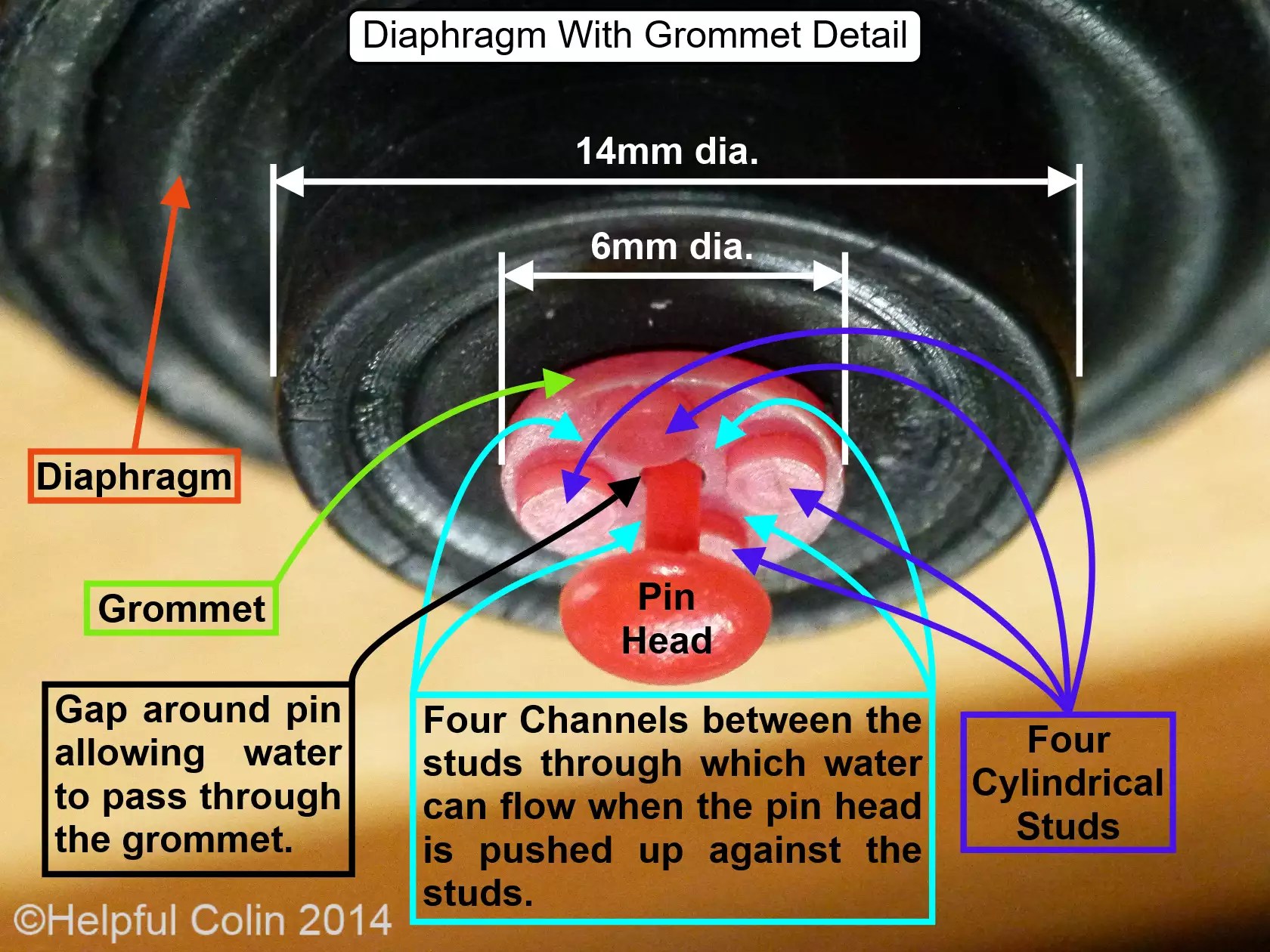
Fig. 7, above, shows the Silent Fill Valve Diaphragm correctly oriented and at an approximate scale of 8:1 on a 94 dots per inch PC monitor. The Restricting Pin is shown hanging down as gravity requires.

In Fig. 7, the Red Grommet in the centre of the Diaphragm is clearly visible with its four moulded cylindrical studs equally spaced around the central 1mm diameter hole. The red plastic Restricting Pin can be seen to be loose in the hole with a very narrow gap around it through which water can pass. The movement of the pin in the hole, and the materials from which the grommet and pin are made, probably prevent calcium deposits forming which might otherwise block the hole.

The four cylindrical studs that prevent the pin head from blocking the hole completely can clearly be seen in Fig. 7. The studs can be seen to be spaced apart leaving Channels for water to pass between them on its way to or from the central hole.

On the other side of the hole (not shown) the Restricting Pin is squashed flat to make it bulge out on two opposite sides. The bulge prevents the pin dropping out through the hole but at the same time allows water to pass easily through the hole on the flattened sides. The pin can move up and down the hole freely covering a distance of 2mm.

4. Calculation of The Silent Fill Valve Diaphragm Areas

Refer to Fig. 5, Fig. 6, Fig. 7 and Fig. 8.

Fig. 8 – Diaphragm Pressure Area Dimensions.

diaphragm dimensions
Fig. 8 – Select this image to enlarge it.

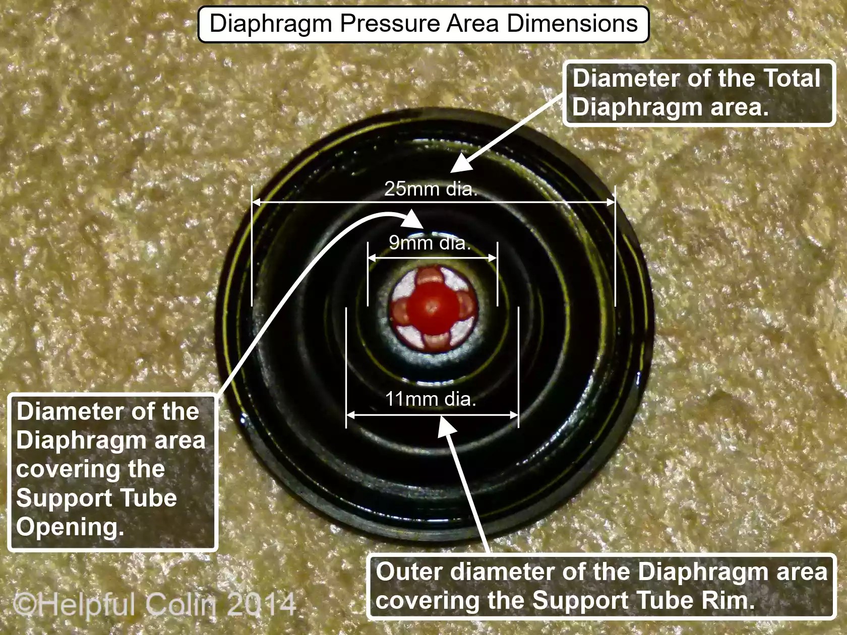
Fig. 8, above, shows the bottom of the Diaphragm with three diameter dimensions 9mm, 11mm and 25mm. These are used in the formulae below to calculate four Diaphragm Areas. In these formulae let:

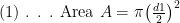
  1. d1 = 9mm which is the diameter of the area that covers the hole in the top of the Support Tube when the valve is closed,
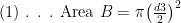
  2. d2 = 11mm which is the outer diameter of the contact area of the rim of the Support Tube (approximately 2mm thick),
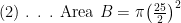
  3. d3 = 25mm which is the diameter of the area of the effective part of the Diaphragm.

From these three dimensions the areas of the Diaphragm covering Waters ‘A’, ‘B’ & ‘C’ in Fig. 5 and the area ‘T’ where the Diaphragm comes into contact with the rim of the Support Tube can all be deduced as shown here with reference to Fig. 6 & Fig. 7:

Calculating The Area of The Diaphragm Above Water ‘A’ in Fig. 5.

\text{(1) . . . Area }A=\pi {{\left( \frac{d1}{2} \right)}^{2}}

\text{(2) . . . Area }A=\pi {{\left( \frac{9}{2} \right)}^{2}}

\text{(3) . . . Area }A=63\text{m}{{\text{m}}^{2}}

Calculating The Area of The Diaphragm Below Water ‘B’ in Fig. 5.

\text{(1) . . . Area }B=\pi {{\left( \frac{d3}{2} \right)}^{2}}

\text{(2) . . . Area }B=\pi {{\left( \frac{25}{2} \right)}^{2}}

\text{(3) . . . Area }B=490\text{m}{{\text{m}}^{2}}

Calculating The Area of The Diaphragm Above Water ‘C’ in Fig. 5.

\text{(1) . . . Area }C=\text{Area }B-\pi {{\left( \frac{d2}{2} \right)}^{2}}

\text{(2) . . . Area }C=490-\pi {{\left( \frac{11}{2} \right)}^{2}}

\text{(3) . . . Area }C=395\text{m}{{\text{m}}^{2}}

Calculating The Area of The Diaphragm Above The Rim of The Support Tube ‘T’ in Fig. 5.

\text{(1) . . . Area }T=\pi {{\left( \frac{d2}{2} \right)}^{2}}-\text{Area }A

\text{(2) . . . Area }T=\pi {{\left( \frac{11}{2} \right)}^{2}}-63

\text{(3) . . . Area }T=32\text{m}{{\text{m}}^{2}}

Referrers

  1. Toilet Silent Fill Valve Repair.

End of Post

Comments

128 responses to “How A Toilet Cistern Silent Fill Valve Works”

  1. lewis avatar
    lewis

    Really helpful and detailed diagrams.Best description of all parts and workings I have ever seen.Carry on the good work.

    1. Helpful Colin avatar

      Thank you Lewis. Your good comment is reward enough for all the effort I put into those drawings.

      1. Trevor Heley avatar

        Very good description and diagrams. Thank you. I am having trouble with my SIAMP silent fill valve.Will only “shut off” if the adjacent sink tap is turned on/off a few times?

        1. Helpful Colin avatar

          Hi Trevor,
          Well I suspect turning the tap on and off is sending shock waves through the water in the pipe which jerk the valve until and get it to close.
          You could try tapping the valve with the cistern lid off to see what happens. Maybe dirt or calcium build up is preventing moving parts from moving smoothly.
          Otherwise you may have low water pressure at the valve.
          Please let us all know what you find.
          Regards, Colin.

  2. Alan avatar
    Alan

    Brilliant description – helped me realise why at first the replacement diaphragm that I fitted wouldn’t work. It was upside down. Thanks very much

  3. Chris avatar
    Chris

    This is one of the best descriptions that I have encountered on a topic that is far from intuitive! Impressive and very he[pful. I did managed to somehow correct my ‘ever flowing’ cistern before I read the article, and now I understand the why and how which is very satisfying!

    1. Helpful Colin avatar

      Thank you Chris for your positive comment.

  4. Prash avatar
    Prash

    fantastic explanation, found this site really useful. I have a problem with trying to replace the diaphram in a bottom entry fill valve only I can’t seem to get the top part off. It doesn’t have a clamping nut. The only picture I can find on the internet of how it looks is at http://www.screwfix.com/p/armitage-shanks-8-bottom-entry-fill-valve/98097. Does anyone know how to remove the top part to replace the diaphram?

    1. Helpful Colin avatar

      Hi Prash,
      I have looked at the picture on Screwfix and another picture of a side entry valve also at Screwfix – http://www.screwfix.com/p/side-entry-fill-valve/64191. Both valves look as if they have the same part capping the diaphragm with the fulcrum for the arm built on it. The side entry valve gives me another viewing angle of the four slightly curved slots in that piece. I suspect that piece is held on with clips of some sort. so it just clicks together. I suspect they might be released by using a blade down some or all of those slots to prise the clips. Check it out and use a magnifying glass if needs be to examine it close up. Good luck.

  5. Mark C avatar
    Mark C

    Silent fill valve explained perfectly. Mine was overfilling and wasting water constantly. Found this website and took it apart, cleaned the diaphragm in warm water washing all the gunk off, re assembled and works perfectly now:-) This could have cost me a huge amount in plumbers fees. Thanks for your expert help.

    1. Helpful Colin avatar

      Hi Mark,
      I’m glad I was of some help. If ever you think you would be better changing the diaphragm don’t think twice about it. They’re only £1.57 on the B&Q website today at: http://www.diy.com/departments/plumbsure-diaphragm-washer-dia30mm/184682_BQ.prd
      Regards from HC.

      1. Bruce avatar
        Bruce

        Hi Colin,

        My diaphragm washer is EXACTLY the same as yours, have absolutely trawled the internet and cannot find a replacement. The one you linked on the B&Q website looks slightly different and is no longer available.

        Do you know where I can buy a washer the same as the one you show? It’s for the screw type inlet valve.

        I’m going mad here! Please help

        1. Helpful Colin avatar

          I’m Sorry Bruce, I don’t know where to get one from. The one with the red pin seems to be obsolete. I’m inclined towards a new valve when I next have to deal with the problem. I’ve eyed one up at B&Q. My systern is extra deep and there is a brand there that comes in two heights, so I think the longer one will do the job.
          Regards, Colin.

  6. Chris brooks avatar
    Chris brooks

    Hi I’m having the same problem as prash and can’t seem to get the clips undone with a fear of snapping the clips

    1. Helpful Colin avatar

      Hi Chris,
      I suspect some valves are made to use and throw away when broken. If you can visit Screwfix you might see if they have one the same. If they do you can risk breaking the clips on yours knowing you can at least replace the whole valve.
      Regards, Colin.
      P.S. I presume you saw my reply to Prash.

  7. Seb avatar
    Seb

    Just fabulous!

  8. Rob avatar
    Rob

    Excellent detail. i opened a Mira shower solenoid valve and couldn’t figure out how the delicate spring in the solenoid could stop mains water pressure. Your diagrams sung the answer.,Nice one!!

  9. Jim Lyons avatar

    Great explanation and graphics. But I have a related question. My toilet fill valve is of a different design, with no pin or pin hole. It has a rubber plug that is pushed down over the inlet opening, and three separate rubber washers of different diameters that mate with three different plastic cylinders. All the washers are mounted on the same shaft between the top, which is pushed down by the float arm, and the bottom plug that stops the inlet flow. I’ve convinced myself this device uses line pressure to finish the closing of the water supply, similar to the device you have explained, but I can’t figure out how. Can you help?
    Jim

    1. Helpful Colin avatar

      Hi Jim,
      Please send a photographed/scanned sketch of a cross section of your valve for me to consider.

      1. Jim Lyons avatar

        Hi Colin
        I have a sketch on a PDF file but I don’t know how to attach it, or send it to you directly. Can you help me with this?

        1. Helpful Colin avatar

          Hi Jim,
          Please send your PDF as an attachment to an email in the same way you would send a picture file. Send the email to helpful.colin@btinternet.com (the address I use for blog related emails). I will then save it on the server and reply again in these comments with a link to your PDF to make it publicly available. Discussion regarding the content of the PDF will then follow in further comment(s).

        2. Helpful Colin avatar

          Hi Jim,
          I have received your sketch of your fill valve. Here it is for all to see. I will now go away and study it.

  10. Brent Davies avatar
    Brent Davies

    Hi Colin, thanks for your explanation – I just could not fathom it out how it worked. The problem I have is similar to others (slow leak when cistern is full), but having taken the diaphragm out to examine it – looks OK so cleaned and put back – I am now in a worse position because the leak is now running at full power,just as if the pinhole is permanently open. Any ideas?

    1. Helpful Colin avatar

      Hi Brent,
      If it is now worse and you really can’t find a hole. I have to ask if you have now put the diaphragm in upside down by mistake (I’m not sure it’s possible) after you looked at it? A new diaphragm is only £1.57 at B&Q in the UK. Plumbsure Diaphragm Washer (Dia)30mm
      Else is the diaphragm sitting correctly and is the clamping nut now cross threaded. If you can remove the arm attached to the float so you can put your finger over the pinhole you will find out of the problem is internal or external. If you can’t stop the water with your finger over the pinhole then something inside the valve is a problem or it is incorrectly assembled. However it won’t stop filling if the float lets the water rise until it goes down the overflow. Then you must adjust the float. Good luck.

  11. Brent Davies avatar
    Brent Davies

    Thanks Colin
    Prior to your reply, I bought a new diaphragm from B&Q and tried that. First of all it’s a slightly different design. The original has an extra flange which sits in a recess on the top, but I tried it anyway by sitting it on the inlet part. Referring to your diagram mine does not have a “red annular diaphragm support”. Replaced the top and this time I got back to the original problem ie. slow leak once main fill is complete implying that the pinhole and arm mechanism is OK. Since then your reply has been received and to confirm the pinhole theory I removed the arm and placing finger over the pinhole – the water continued at full power. I tried this with both the original diaphragm and the B&Q one but to no avail. So the B&Q one now does not work at all ie water at full pressure. As for cross threading top, this is quarter turn snap lock fitting which sits correctly. Looks like a new inlet valve. This has happened before (6 months ago) on a different WC and in that instance I just replaced the lot.

    1. Helpful Colin avatar

      Hi Brent,
      I have to say that with these modern fill valves the replacement diaphragm must be exactly the correct one the manufacturer intended. I don’t believe any are interchangeable. I suspect you may be using the wrong type. B&Q do sell similar but different diaphragms, e.g. Plumbsure Float Valve Diaphragm Washer (Dia)25mm and Plumbsure Ballvalve Diaphragm Washer (Dia)30mm, Pack of 2
      I have not had experience of all types so I am sorry if I have not been very helpful. Good luck.

      1. Brent Davies avatar
        Brent Davies

        Thanks again Colin
        Neither of those suggestions are compatible. I have now replaced the whole unit.
        Thanks for your help anyway.

  12. eric james avatar
    eric james

    Best ever description of something simple yet complex that I have ever read.Thank you very much for your effort

    1. Helpful Colin avatar

      Thanks Eric,
      Your comment is much appreciated. I have spotted room for improvement and the recently introduced Fill Speed graph is part of that. I have previously implied that the valve closes slowly when in fact it doesn’t start closing until late in the fill cycle but it closes rapidly once it starts closing.

  13. lalji avatar
    lalji

    hi colin i am looking for a spare part that u r holding in your hand,it is inlet valve that is not functioning.water coming in to the pan constant

    1. Helpful Colin avatar

      Hi Lalji,

      The part you can see me holding, in the feature image, is the diaphragm. This is a flexible rubber part which is held firm at the edge, but the thick centre part can move up and down to either shut off the water supply or let the water through to fill the cistern. Because the centre moves up and down every time the cistern fills with water the thin rubber attaching the centre to the edge eventually rips and lets the water through all of the time. That is when you have to replace the diaphragm with another of exactly the same type.

      Diaphragms that look different are different and cannot replace yours. If yours is like mine with a red pin in the middle then I advise you to replace it with one with a red pin. If yours is not like mine and has a white pin in the middle I advise you to search for an exact same one with a white pin in the middle. If it doesn’t have any pin at all then buy one without any pin at all.

      I got my replacement diaphragm from B&Q. If you read my other post entitled, “Toilet Silent Fill Valve Repair,” you will see I spoke about it there. If you go to the B&Q website http://www.diy.com/ and search for ‘diaphragm’ you should be able to find it. (I just tried it.)

      Good luck.

  14. Dublin Plumber avatar

    Great post Colin, plenty of detail and pictures, enjoyed reading it.

  15. DavidB avatar
    DavidB

    Thanks very much for the excellent description of how these things work! I have a system with low input (mains) pressure and it never seems to seal… filling to the overflow and then wasting water. Would I be better off with another fill valve system?

    1. Helpful Colin avatar

      Hi David,

      Sorry to hear you have low pressure. Perhaps you should get your supplier to check it. It may be below the level they guarantee to provide or they may be able to give you advice. I don’t know if another type of fill valve would be better or not. Maybe there is a problem with the one you have got. Does the water shut off if you pull the float up and hold it up. You could use a piece of string and an elastic band to pull it up and tie it to something above your cistern. If the water does stop flowing try adjusting the float. If it doesn’t change the diaphragm.

  16. Fiona avatar
    Fiona

    Hi colin. Fitted a new univalve filler yesterday similar to your pic ..the water seems to trickle out of the top and nothing through the fill arm/plastic slieve and is taking half hour to refil the cistern….any ideas or is it a faulty one? Thanks

    1. Helpful Colin avatar

      Hi Fiona,
      Why not take it back to the store and have it replaced? If you’ve fitted it correctly then it’s not fit for purpose. Alternatively dismantle it and try to work out how it should work and why the water is not passing through correctly. If it has a diaphragm like mine (or similar) has it been assembled incorrectly with the diaphragm upside down? Are there some holes missing in the plastic mouldings?
      Good luck.
      Regards HC.

  17. Steve Bradford avatar
    Steve Bradford

    Hi Colin,
    I have a question regarding my AMSTD silent filling valve that works on this principle of using mains pressure to move the diaphragm controlled by the opening or closing of the weep hole. The only difference I see is the valve is mounted horizontally so there is no gravity assist for the small restrictor valve in the diaphragm.

    If during the filling cycle I lift the float, the flow into the cistern is not diminished no matter how soft or hard I lift float or for how long.
    However if I let go of the float and allow the level rise to the fill level the valve works correctly and halts the flow so all is well.

    It was only through exercising the routine maintenance precaution of fitting the right new rubbers parts correctly to the cisterns of rental properties that I noticed this phenomenon.

    It was after fitting the new rubbers that I turned the water on and lifted the float to check the flow would be stemmed when to my dismay it did not.
    I double checked my installation and tried again several times to no avail even after fitting the old rubbers again.
    I removed the lever holding the weep hole seal to try and block it with my finger but unfortunately the pivot supports prevent this, but I feel sure the new rubber is effective.

    After a while in desperation I allowed the cistern to fill to the fill level and to my surprise the valves worked correctly stemming the flow.

    So no real problem, except that having thought I understood the principle of operation and having had it confirmed by your excellent article I fear I must be missing something.
    But what?

    This phenomena is consistently repeatable and I have run out of ideas.

    Any ideas you have would be very welcome.

    Thank you for your time,
    Steve Bradford.

    1. Helpful Colin avatar

      Hi Steve,
      Sorry for my late reply.
      I read your comment afresh and I can’t understand how it works either. So I ask, “Can you control it manually by lifting the float when it’s very nearly full?” If you can that would suggest that its workings are affected by the water pressure in the cistern caused by the depth of water in it. I would have to handle this type of valve to get a better idea.
      Regards, Colin.

      1. Steve Bradford avatar
        Steve Bradford

        Hi Colin,
        Thank you for your reply.

        The cistern valve is a Dudley Hydroflo where the valve mechanism is horizontal and the small float works via a crank based on the principle you describe so well.
        A quick search on e-bay would show you the design and the replacement diaphragms available that I fitted.

        I did try the method you describe lifting the float just before the fill level is reached and it will work, just not always repeatable.

        Allowing the system to fill from empty in it’s own time works reliably and has done so since fitting the new diaphragm before Christmas.

        I am at a loss in understanding the dynamics of the system as the principle of pressure equalisation across the diaphragm as the float rises and unseating the control valve forcing the filling valve to close due to the difference in effective area seems sound.

        The cistern is in a rental property and fitting a new diaphragms is good preventative maintenance, but I would not have fitted a new diaphragm if the system had not failed the manual lift test. Of course several days passed before I recieved the new diaphragms and you can imagine my surprise when the new ones fitted to both cisterns both failed the manual lift tests.
        I admit it took me a while to find the anomaly where both would work well when allowing a full fill.

        So it is not a problem except for the frustration of not understanding the difference. I am sure it is not mechanical and cannot reconcile a back pressure effect up through the flexable anti-syphon silent fill tube.

        The good news is I am not losing so much sleep any more but it would be nice to know what I am missing.
        Thanks again,
        Steve Bradford.

  18. Gordon avatar
    Gordon

    Cracked it- but only with your help Colin,old diaphragm completely nuked in as much the outer edge had become detached which I had not realised. Went to a local supplier who said “My that’s taken a hammering, it should be much bigger than that”. So on investigation found the outer remnants still in situ in the valve, replaced said diaphragm and behold, didn’t work. Stupid me had inserted it upside down, and now it works fine. Let the incoming water shut the valve off, as lifting the float by itself won’t stop the incoming water not like the old fashioned systems.
    Once again Colin thanks.

    1. Helpful Colin avatar

      Hi Gordon,
      I’m glad you had success.
      Maybe other people have had difficulty when not realising that a piece of the original diaphragm was left in situ when a new one was inserted.
      Regards, HC.

  19. S Thompson avatar
    S Thompson

    The most useful description of a diaphragm I have ever seen. Thanks for making it understandable.

  20. Mal Prodger avatar
    Mal Prodger

    Very explicit diagram which removes the mystery of these valves. My problem is very slow filling which has been the case for a few months. After reading your blog I decided to fix it. I changed the diaphragm (more than once!) and checked the pinhole was clear etc. All to no avail. On first fill after inserting the diaphram everything works but then it resumes to slow filling via the pinhole. I am assuming that the diaphragm is not in the closed position on the first fill but subsequently retains the closed position with the pin dropped to allow water through the pinhole. Any clues?
    Mal

    1. Helpful Colin avatar

      Hi Mal,
      This sounds like there might not be enough water pressure underneath the diaphragm to lift it up and push water into the cistern. The diaphragm has a natural tendency to take a flat closed position when there is no water pressure.
      You could turn off the water supply, uncouple the pipe from the inlet valve, point it into a container and turn the water back on to check if there is plenty of pressure to drive water along the pipe. If there is little or no pressure fix it. Are your pipes blocked with calcium (this happens in hard water areas)?
      If there is plenty of pressure then check there is not a blockage in the pipe of the inlet valve leading up to the diaphragm. A blockage could be caused by debris driven along the pipe by the flowing water. If there is a built in restriction in the pipe to slow water flow in high pressure areas the small gap left for water may be blocked.
      With the diaphragm and inlet pipe removed it may be possible to poke a wire down the inlet valve pipe or shine a light up it to check it is clear. The alternative would be to remove it from the cistern so you could inspect it on a bench.
      I hope this is helpful.
      Regards, Colin.

  21. Mal Prodger avatar
    Mal Prodger

    Apologies for my appalling typing – should check before send! Should have said ” I am assuming that the diaphragm is not in the closed position on the first fill but subsequently retains the closed position with the pin dropped to allow water through the pinhole.

    1. Helpful Colin avatar

      Hi Mal
      No worries. I have the power to edit it. Check it now.
      Sorry I haven’t got a good reply for you yet.
      Regards, Colin.

      1. Mal Prodger avatar
        Mal Prodger

        I have come to the conclusion that there is inadequate pressure to “open” the diaphragm. I have approx 4metres of head feeding various items. If I tweak the inline valve to induce a kind of hammer effect this causes the valve to open so I deduce that there is almost enough head. I cannot find any reliable information on the minimum pressure required to operate the valve so am reluctant to commit to a replacement valve such as the SIAMP 99B Low Pressure unit

        1. Helpful Colin avatar

          Hi Mal,
          It’s nice to know you’ve identified the problem.
          Water pressure can be increased using a pump. Obviously you don’t want a pump using electricity continuously. There are pumps which turn on when a flow commences and then they boost the flow. That may not work in this case due to the initial flow being very slow to zero.
          You could consider a basic ball valve. Modern ones are plastic and can be mounted in the bottom of a cistern, as well as the side, and can have small floats. You would have to carefully select one. A builder’s or plumber’s merchant may be able to advise you and show you different ones. I’m suggesting this because they use a simple valve which doesn’t resist the water flow until it’s forced shut when the float rises sufficiently.
          Regarding the SIAMP 99B: I looked at it on http://www.siamp.co.uk/compact-99b/ and the minimum pressure at which it will work is 0.5bar. I then went to http://www.convertunits.com/from/bar/to/meters+head and it converted to a 5m head. So that makes it unsuitable for you.
          Good luck with this one Mal.

          Regards, Colin.

          1. Mal Prodger avatar
            Mal Prodger

            Thank you for your advice Colin. I have very little room in the cistern for a ball valve & arm. I have spoken to SIAMP and they tell me that the 99T will operate at 0.2 bar which should work for me.. Cross fingers.
            Regards
            Mal

          2. Mal prodger avatar
            Mal prodger

            Hooray! The SIAMP 99T is doing the job.

            1. Helpful Colin avatar

              Well done Mal,
              I’m glad you’ve been successful.
              Have a good weekend.
              Kind regards, Colin.

  22. John Walker avatar
    John Walker

    In answer to prash’s question about removing the top. The clips fit under a circular shelf, with two ‘flats’ diametrically opposite each other. Twist the top until the clips are over the ‘flats’ and you can pull the top off. It still a bit hard to do but it does come off without the clips breaking.

  23. […] toilet fill valve mechanisms have an adjustable stirrup which helps to adjust the height under the tank lid. So check it before […]

  24. gary alston avatar
    gary alston

    hi colin I have the screw inlet valve with a red diaphragm. when ordering a replacement I can only get one with a white pin and this doesn’t work.b+q no lonher stock the red pin.what do I do please.thank you Gary

    1. Helpful Colin avatar

      Hi Gary,
      You referred to a red diaphragm. I presume you mean a black diaphragm with a red pin.
      Well I hope this saves your bacon: https://www.screwfix.com/p/arctic-products-hushflow-washer/1331j
      Regards, Colin.

      1. gary alston avatar
        gary alston

        Thank you. for the reply .unfortunatly I already tried this one but to no avail.not sure where I go from here..Gary

          1. gary alston avatar
            gary alston

            Colin.I think you’ve cracked it .I’ll order now and let you know.much appreciated.thank you. Gary

            1. Helpful Colin avatar

              Hi Gary,
              I hope it goes well. I’ve modified my post, “Repairing A Toilet Silent Fill Valve.” to fit with today’s discussion.
              Regards, Colin.

              1. gary alston avatar
                gary alston

                Thank you very much for your help.Best Regards.Gary

              2. gary alston avatar
                gary alston

                hi colin.before I ordered the washer you suggested I back flushed the inlet valve after reading your suggestion about lack of filling pressure. low and behold.you solved it.it wasn’t the washer after all.you’ve saved me a lot of money.thank you for your advice Kind Regards
                Gary

                1. Helpful Colin avatar

                  Garry – I’m pleased to have been some help.
                  Have a good spring and summer.
                  Regards, Colin.

  25. Peter avatar
    Peter

    Absolutely fantastic presentation and explanation Colin. Clearly you have a passion for providing technical detail and its very much appreciated.

  26. Clive Jones avatar
    Clive Jones

    Hello, I am ‘blown away’ by the level of technical detail here. But I couldn’t find the answer to my problem: the water running into my cistern shuts off very suddenly when the cistern stops filling, and a shock wave goes through the plumbing of the whole flat! I am worried that I will soon have a fractured joint somewhere. Thanks if you can help. Clive, Watford

    1. Helpful Colin avatar

      Hi Clive,

      This problem is known as ‘hammering’. You’ll probably get the same effect if you turn any tap on your system off quickly enough.

      As you probably understand liquids cannot be compressed so you get this sound when your taps and valves try to compress the water when they shut off. What you need is an air bubble in the pipe because gas can be compressed so it takes up the energy of the shock wave.

      You can buy devices which attach to the pipe and either hold air or a springy piston. They absorb the shockwave energy. Look here: https://www.google.co.uk/search?q=how+to+stop+pipe+hammering&ie=&oe=

      Regards, Colin.

  27. Tachi avatar
    Tachi

    Hi Clive,
    Adjust the height of the Buoyant may be? so the diaphram won’t fill up and expand too quick?

  28. tachi avatar
    tachi

    Excellent explanation Colin, that amount of details is unprecedented.
    I do have a few questions after reading:
    1/ I take it that the Buoyant now have no control to the fill level? (pulling up the Buoyant during fill won’t stop filling as main water pressure can push up the diaphragm)
    2/ What is the function of the flexible outlet pipe?

    1. Helpful Colin avatar

      Hi Tachi,

      What you are calling the Buoyant is named in English as ‘The Float’. When resting in the water the float is a buoyant thing like boats or corks are buoyant things.

      Answer 1: Pulling the float up does shut off the water. It blocks the pinhole which in turn activates the diaphragm. Once the pinhole is blocked off the pressure on both sides of the diaphragm equalises due to the high pressure water leaking through the hole with the red plastic pin in it which is a loose fit and not watertight. When the water pressure is equal on both sides of the diaphragm it closes due to its own springiness which makes it move into the closed position, i.e. the position the diaphragm has when it comes out of the manufacturer’s mould. It naturally takes up this position when the sum of the forces above and below are zero.

      Answer 2: Outlet pipes were solid tubes at one time. If the incoming water is released below the surface it’s silent. A sold tube may allow syphoning back from the header tank into the supply pipe under extraordinary conditions. Try making a syphon with a flexible pipe that can go flat like a plastic bag. Water companies (in the UK at least) won’t tolerate any risk of water syphoning back into the supply in case the water in the header tank has become foul and could corrupt the fresh water in the supply pipework going to drinking water taps.

      Regards, Colin.

  29. Bob A avatar
    Bob A

    Phenomenally helpful, this is just what i was looking for. Many thanks!

  30. Ewan avatar
    Ewan

    Hi Colin,

    In the process of trying to replace my hushflow diaphragm (reported in the other thread), I noticed that the polythene outlet pipe is all split and water is spraying out when the cistern is filling. Do you know if it’s possible to get replacements anywhere? Or any suggestions for alternatives? It’s not much of a problem but it could help reduce the noise a little.

    1. Helpful Colin avatar

      Hi Ewan,

      I’m glad you’ve found the cause of the spraying water you mentioned earlier. I think you will have to fix it by bodging it.

      I received the diaphragms I ordered. They are very similar to my old ones and have white pins. Here is a picture of them:

      3 New Diaphragms With White Pins.

      I’ll test one when I can find a moment and let you know if it works.

      Regards, Colin.

    2. Helpful Colin avatar

      Hi Ewan,
      I apologise for not passing this message on sooner. This is an answer I gave to another comenter, to my post mentioned below, today.
      I modified the post “Repairing A Toilet Silent Fill Valve” a few months ago after testing diaphragms with white pins in my fill valve which should use a red pin diaphragm. Please read teh section “Replacing Fill Valve Diaphragms In General“. It explains how they may be made to work.
      Regards, Colin.

  31. Maurice avatar
    Maurice

    Great post Colin Well done.
    I have a standard brass ball valve filling a plastic cistern. It works fine.
    I also have a Brass 1-25LT Water Flow Sensor Switch 1/2″ Hall Effect Meter Control DC 5-15V https://www.ebay.co.uk/itm/Brass-1-25LT-Water-Flow-Sensor-Switch-1-2-Hall-Effect-Meter-Control-DC-5-15V/123827868928?hash=item1cd4b75500:g:27sAAOSwctJcAwpp to measure my water usage via Raspberry pi.
    This works fine except when the cistern is near the end of filling and dribbles in the last 20 litres.
    Is there a ball valve which would snap open and snap closed or stop when the flow rate is below 1 litre / minute
    Thanks
    Maurice

    1. Maurice avatar
      Maurice

      To answer my own question.
      Fitted a Fluidmaster 747UK .
      This has greatly reduced the dribbling into the tank and is very quiet.
      It isn’t 100% snap open or snap close, but it is 95% of the way there.
      I suspect for 100% I would need to use an electrical solenoid.

      1. Helpful Colin avatar

        Hi Maurice,
        Sorry I didn’t get around to replying to your previous comment. However it’s nice to know you’ve found a solution.
        Regards, Colin.

  32. Matt Hall avatar
    Matt Hall

    Hi Colin,
    Thank you ever so much for this beautiful explanation of how this mysterious valve works. After much head-scratching I had it more or less worked out but this explains it much better than I ever could and with lovely diagrams too.
    I had a leak into the pan which I assumed was from the flush valve – confirmed by seeing the cistern empty overnight with the feed turned off. Sadly, repairing that did not cure my problem as the inlet valve was also leaking. All the rubber components of both valves had perished.
    After changing the diaphragm washer in the inlet valve there was still a dribble so I had to take the top arm off (not easy, a delicate use of brute force) to get to the small rubber component which stops up the pin-hole once the float comes fully up.
    Fingers crossed that my repair will work as I can find nowhere to purchase a new little rubber stopper.

    1. Helpful Colin avatar

      Hi Matt,
      Perseverence pays off. I doubt you’ll get another rubber stopper unless you know someone who is scrapping a similar item. But of course it won’t be new. I’m still managing with my original one.
      Regards, Colin.

  33. Roger Paulson avatar
    Roger Paulson

    Hi Colin
    A problem I am sure you can sort. I live in a bungalow so the head of water from the cold tank to the taps on upstairs sink/toilet etc is very small, something like 3ft. When I fitted new taps and toilets upstairs several years ago I then found the low head was giving low water flow, disc valves. To solve the problem I fitted a twin impeller pump which transformed the water flows and everything has been ok since.
    Just recently my two upstairs toilets got to a point where they will not fill after flushing without I open the tap on the sink to create enough flow to close the pump flow reed switches. I bought one new diaphragm which I could try in both toilets to check it solved the problem, if ok I would get another. The caps for diaphragm are click 1/4 turn not screw.
    I fitted the diaphragm in one toilet, the pump starts and the toilet fills perfectly, after about 10 seconds the pump gives a quick burst of water then stops, this repeats continually in roughly 10 second intervals. It does the same on both toilets. I thought at first it may be the sealing bung over the pin hole but then realised it works ok with the old diaphragms. Could I have the wrong diaphragm? Toilet is armitage shanks ideal standard about 6 years old, the diaphragm looks identical except the centre pin is white not red, part number is SV32967.
    Any thoughts. Regards Roger

    1. Helpful Colin avatar

      Hi Roger,
      I think that if you had red pin diaphragms originally you shouldn’t change them for white. However red pin diaphragms are like gold dust. White seems to be all I can get. I expect to have to change my fill valves eventually.
      In the mean time:
      I modified the post “Repairing A Toilet Silent Fill Valve” a few months ago after testing diaphragms with white pins in my fill valve which should use a red pin diaphragm. Please read the section “Replacing Fill Valve Diaphragms In General“. It explains how they may be made to work.
      Regards, Colin.

      1. Roger Paulson avatar
        Roger Paulson

        Hi Colin
        Thanks for your reply. My fill valve assembly on both toilets have the 1/4 turn locking cap and both are fitted with red pins, you suggest red pins are fitted to valve assemblies with screw caps, which is obviously not the case.
        I will search out a diaphragm with a red pin and see if it works.

        Will let you know outcome.
        Regards. Roger

        1. Helpful Colin avatar

          Hi Roger,
          The one I have has a screw on cap. I got it in 2006/7 and it came with a red pin. These screw-on cap ones are the old style. Then people started telling me about theirs, which turn out to have a Twist Lock cap. All the info I have about those has come from other people like yourself. So I am at everyones mercy with them. I don’t have my own facts. If yours has a red pin then fare enough. You,re not the first to tell me.
          With regard to diaphragms: I am in posession of red and white and wrote about them to describe their differences. However I don’t really know which valves are supposed to use the white ones. I’d love to know.
          Regards, Colin.

          1. Roger Paulson avatar
            Roger Paulson

            Hi Colin
            Have done some more digging. I have talked to Ideal Standard to find out exactly what is what.
            Firstly the colour of the pin has no bearing on which valve fits where. The diaphragms are different for the screw or 1/4 turn cap valve, they say the diaphragms for the screw cap assembly are no longer made, however some sites say they are still available
            For a 1/4 turn cap valve there is a kit, which has 5 parts in it, the diaphragm valve, rubber bung for the lever to seal the pin hole, flow restrictor and two other parts which I am not quite sure where they fit. The part number for the kit is SV90167, the Ideal Price is £8.30 + VAT, I have found that PTS Plumbing keep them. Price is £6.89 incl VAT. One of the Derby PTS sites has stock so I will get one.
            Fixthebog sell diaphragms for 1/4 turn cap singly, part No FTB2654 and they are £3.67 each + VAT & postage. They also sell the diaphragms for the screw cap singly, part No FTB323 and they are £4.15 + VAT & postage. They have a very good web site which explains the red & white pins and which part fits which head type.
            I asked Ideal Standard about dimensions for the two diaphragms but they could not give that info. When I get the kit I will measure the diaphragm and send you details.
            If you need further info/clarification ring Ideal Standard on 01482 346 461, they are very helpful.

            Regards Roger

            1. Helpful Colin avatar

              Hi Roger,
              Thank you for your efforts here, and for passing on this info.
              The more facts the better. I will edit my posts accordingly.
              I have heard of Fixthebog. I might have ordered something from them before now.
              For myself – If I can get a few diaphragms in hand I’ll be able to continue with my original fill valve for a few years.
              Now would be a good time to change it, actually, because I have the cistern off to replace the old rusty coupling plate. I’m really hoping the new shiny one is made of stainless steel. My assessment is that it’s not stamped out of a sheet of ready plated steel (the edge finish is identical to the surface finish) and it would be expensive to plate individuals post press. It’s a propper Armitage Shanks/Ideal Standard one. The packet has threee of their leaflets in it. One of those is a “Univalve” with detailed diagrams. It’s the Twist Lock type.
              Regards, Colin.

  34. Graham Clark avatar
    Graham Clark

    Hi, Colin. Thanks very much for taking the trouble to explain exactly how a modern ‘silent’ inlet valve works. As with so many other responders, yours is by far the clearest description I’ve seen. Having recently (and successfully, to my relief) replaced an entire 5-year-old malfunctioning inlet valve unit for £11 from Amazon (just replacing the diaphragm for £3.56 hadn’t worked), I was uncomfortable knowing that I really didn’t understand what I’d been looking at. I do, now, thanks to your comprehensive explanation of how pressure differences operate on the diaphragm via tiny holes in the mechanism.
    Regards,
    Graham

  35. Paul Burbidge avatar
    Paul Burbidge

    Hi, Colin. Many thanks for the comprehensive explanation of how a silent ball valve works. I’ve got an Ideal Standard valve, circa 2,000AD, with a horizontal, bottom feed body, screw end caps, which, just recently, has been constantly dribbling.
    Initially, I dismantled it and found that the conical inlet filter had lost all the gauze mesh, and the diaphragm was ‘crusty’ (hard water area). I gently scrubbed the crust off with a tooth-brush, reassembled it and it worked fine for a couple of weeks.
    Then it started dribbling again, getting worse as the cistern level rose above normal. Ideal Standard recommended I buy a kit (SV90167) from fastpart which I bought, and it came with lots of parts I didn’t recognise, and a different diaphragm, without the red part, but I fitted it anyway and it shut-off briefly at the normal level, but started dripping slowly and got faster as the cistern over-filled.
    From your explanation, I think it must be the rubber pad on the inner end of the float arm, which covers the pin-hole. As the float and the arm rise above the horizontal, the leverage on the pad will start easing off, the higher the float the more it eases off. Am I right here ?.
    In the absence of a replacement pad, which isn’t shown on the ‘exploded diagram’ that came with the original valve, could I fix it by sticking a thin disk of rubber on the face of the pad, or putting something under the pad to push it forward a bit ?.
    I have to turn the house water-supply off overnight to stop running up the water bill; no isolating valve was fitted because it’s all straight off the mains with no storage tank in the loft.

    1. Helpful Colin avatar

      Hi Paul,
      When you say it’s dribbling I presume you mean water perpetually enters the cistern until it overflows. In which case you need to try and close the pinhole manually to test the situation. You can try pressing the bung end of the arm down onto it or, if you can remove the arm just cover it with your finger. If closing that hole DOESN’T stop it filling then something else is failing and letting water in. If it DOES stop it filling you need to adjust the float. Turn the float adjusting screw so that you force the float down into the water. The water will then apply a greater force to close the pinhole valve.
      What you suggest about padding out the rubber bung, which shuts the pinhole, is correct. This bung does get a dimple in it over time. I once took mine out to have a look at it. I expected it would be a solid cylinder of rubber such that I could invert it and use the other end. I found it wasn’t solid. It has a hole in the opposite end which fits over a plastic pin moulded into the arm. I still use the same bung and the dimple hasn’t been a problem in the long run.
      All my problems over the years have been due to the diaphragm rubber splitting or small adjustment being required to the float position. Unfortunately the inability to get the correct diaphragms now works against us all.
      Good Luck.
      Regards, Colin.

  36. Paul Burbidge avatar
    Paul Burbidge

    Hi, Colin, thanks for your thoughts. There’s now no position of the float arm where the water coming out of the top of the valve body is totally stopped, as it should be when the arm is horizontal. The weather is too nice, at present, to tinker, so I’m living with it, waiting for a rainy day, but first attempt will be to fully block the pinhole as you suggest. Watch this space. Regards. Paul

    1. Helpful Colin avatar

      Hi Paul,
      May I refer you to post “Repairing A Toilet Silent Fill Valve” and the paragraph below Pic.13. This advises to be careful not to break the plastic fulcrum pivot supports when prising the arm from them to gain access to the pinhole.
      Good luck.
      Regards, Colin.

      1. Paul Burbidge avatar
        Paul Burbidge

        Hello Colin,
        Thank you for the caution about the pivot supports, I’ve been gentle with it all along and have avoided breaking anything. I think I’ve got there now. There was the tiniest of dimples in the end of the little 6mm dia x 6mm long pad on the inner end of the float-arm, and I found a new one in the kit SV90167. didn’t notice it before. I think it’s what Ideal Standard call a ‘billet’, but there’s no parts list for the items in the kit so I can’t be sure. I replaced the pad and it all seems to be working OK (at the moment).
        However, before I replaced it, I was in another room and suddenly heard the water pouring into the cistern full-bore, so I shut it off at the mains, yet again, and found that the newly replaced diaphragm had suddenly decided to split and develop a bulge. I hadn’t touched it since installing it earlier in the week. Good job I was at home when it happened otherwise my water-bill . . . . .
        I refitted the original 20yr-old diaphagm, the one with the red section on it, and, as of a couple of minutes OK, it’s still OK. Fingers crossed.
        I’m not sure if I might have to get the incoming water pressure checked some time, because, with the house stop tap turned off, the cistern empty and the quiet-ballvalve removed from the top of the stem, water still wells gentle out of the stem, as if the stop-tap can’t shut it off completely. I have a similarly continually dripping hose connected to an outside tap, like the pressure is too great for the taps to completely work.
        There’s a water-meter in the pavement outside, would this have a pressure regulator associated with it ?. Just wondering.
        Regards.
        Paul

        1. Helpful Colin avatar

          Hi Paul,
          Well done.
          You will find, I am sure, that stop cocks are an imperfect thing. Like many things in this world they’re OK when new but years down the line and they are seldom used and get corroded, calcified, etc. so a complete shut off is difficult.
          Often when working on a water supply with a leaky stop cock you can eliminate the water from your work area by turning on a tap at a lower level to drain the leaking water away from pipes at the height you’re working at.
          Sometimes a stop cock just needs freeing up by opening and closing it a few times with the hope you can close it a bit more each time. Turning the water off when you go on holiday helps in this respect. Otherwise it might not be turned off in 10 years. They have a rubber washer like a tap washer which may need replacing. To do that you have to turn the water of in the street so that you can dismantle or change the stop cock.
          My advice is to be careful what you do with them. You may want to apply a wrench to turn it but if anything breaks you can end up with a gusher which you cannot stop. I leave the damage caused to you imagination.
          P.S. I don’t think you’ll find any water regulator out in the street. Its not like a gas supply where pressure regulation is more sophisticated. With water think Victorian era.
          Regards, Colin.

  37. Paul Burbidge avatar
    Paul Burbidge

    I give up !. Dripping again, where’s the toast ?.

    After flushing the contents of the cistern this morning, it refilled to the correct level, with no surplus drips for a few minutes. Throughout the day, with no further flushes, it has commenced dripping again, the speed of drip slowly increasing, so that, 12 hours later, there is a noticeable ripple in the toilet bowl from the water now running down the overflow.
    In desperation, I have fitted a bicycle puncture patch between the top of the stand-pipe and the body of the valve, so that the water is blocked off – no isolating valve, remember ?.
    Further flushing of the toilet will now be via a bucket filled from a tap. (What makes you think I live alone ?). Maybe I’ll get a plumber in to replace the whole ball-valve assembly when the coronavirus is over.
    Cheers. Paul

  38. Jacopo avatar
    Jacopo

    Hello Colin,
    Amazing explanation!
    I have just fitted a side entry fill valve; the problem is that is not silent at all: when it opens and when it shuts, it makes a funny noise (like a fart ahah).
    There are two filters with pressure reducers that are supposed to go inside; I did manage to reduce the noise by moving one of those farther outwards but then I started having water hammer. Now I’ve taken it apart again and it’s back to the other noise. What can I do?

    1. Helpful Colin avatar

      Hi Jacopo,
      You may have found the best way to silence your valve but now you have a hammering noise when the water supply is finally shut off.
      Well there are devices made to stop that. They are called “water hammer arresters”.
      I think they have a chamber with air separated from the water by a diaphragm. The air is under pressure similar to the water pressure (like having the same pressure on both sides of your eardrum). When the shockwave, sent down the water in the pipe, reaches the arrester its energy passes through the diaphragm and into the pressurised air. It’s dissipated by compressing the air a bit more and heating it (by a very small amount). Whilst in the water the energy can’t be dissipated because like a solid water can’t be compressed. Without the arrester the energy is dissipated by rattling other items plumbed in the pipework.
      My advice is to search for “water hammer arresters” and consider plumbing one in near to your cistern. When I say near, I mean in the same room but out of site as opposed to putting one at the other side of your house.
      Regards, Colin.

      1. Jacopo avatar
        Jacopo

        Hi Colin,
        this is the one I fitted
        https://media.screwfix.com/is/image//ae235?src=ae235/64191_A1&$prodImageMedium$
        It turns out removing the filter and then manually opening and closing the valve and then refitting the filter seems to have fixed it; maybe there was some air trapped somewhere?

  39. Martin Crosby avatar
    Martin Crosby

    Hi Colin
    Great website, very informative.
    I’ve got an Ideal Standard toilet, I’m trying everywhere to get an old style silent fill valve (exactly like the one you’re holding on your home page) any chance you can help?
    Rgds
    Martin

    1. Helpful Colin avatar

      Hi Martin,
      Here is an example of a possible replacement: Ideal Standard Genuine SV81767 Univalve 237mm Bottom Entry Ballvalve Quiet Fill
      You will have to determine if this is the correct height for you at 237mm. I think this is a short version compared to mine which measures 300mm from the inside bottom of the cistern to the top pf the clamping nut.
      Here is a 265mm version: Armitage Shanks 1/2″ BSP Univalve QT Bottom Inlet Float Valve SV81767
      Best of all might be this version with adjustable height: Replacement INLET VALVE for use in IDEAL STANDARD WC toilet cisterns
      When I have to replace mine I might check out Viva Skylo valves some of which have adjustable height too, e.g. The Viva Skylo Bottom Entry and Viva Skylo Dual Entry.
      Regards, Colin.

  40. Ian Hobday avatar
    Ian Hobday

    Thanks Colin for helping me to understand how the valve operated. I had been teasing my brain to try to work it out for myself. I wonder how long it took the inventor of the valve to get it to a reliable production version? The operation of the needle in allowing “the last drop” to squeeze through, is the genius piece of the whole unit.

  41. Rod Day avatar
    Rod Day

    Hi Colin Explanation is great. I have most of the water coming out of the end of the output tube rather than down the flexible flat anti syphon tube so the toilet is not silent. What is the problem please. The toilet does not overflow and this is the second one I have fitted and both had he same problem. Many thanks for your help. Kind regards Rod

    1. Helpful Colin avatar

      Hi Rod,
      Well, from what you’ve said I think something is broken or (if new) not correctly assembled by the manufacturer. Has the flexible anti-syphon tube split open with age near to the output tube. If your valves are new you should get them replaced under guarantee.
      I would expect the cistern to fill as normal and the rising float to cut off the water as normal, but yes it will be noisy. If you choose to repair them you may have to invent a way to do it.
      In my case the anti-syphon tube is sealed to the end of the solid output tube. The output tube has a short right-angled bend downwards just before the flexible tube attaches.
      The silence comes from the water emerging from the anti syphon tube under water so you can’t hear the water coming out.
      I remember some old brass ball valves had solid plastic pipes going under the water but of course they could syphon back into the mains under adverse pressure conditions.
      Good luck.
      Regards, Colin.

      1. Rod avatar
        Rod

        Many thanks Colin. I’ll take it apart and have a look

  42. Douglas Pinto avatar
    Douglas Pinto

    I have a Gebrit 380 Impuls side Inlet valve that was not shutting off. It has an upper floating tray that holds the float adjusting screw. This tray seemed to restrict the upward movement of the float. To test this I was able to remove the upper tray and the float arm is able to shut off the flow.
    Your detailed description was a great help in understanding how the silent flow shut off works.
    However, I still not clear why that upper tray is needed.

    1. Helpful Colin avatar

      Hi Douglas,
      I haven’t seen a Geberit 380 Impuls except in internet sales pictures and video. I can see the ‘Tray’ you talk about. Looking at the shape of it with the ‘V’ hopper at one end I suspect it is there to catch drips of water that otherwise drip directly into the cistern water and make a disturbing dripping noise at night when people are trying to sleep. If you’re happy with it when the tray is removed then I’m sure it will be OK.
      Regards, Colin.

  43. Joo Beng avatar
    Joo Beng

    Dear Helpful Colin,

    After scouring the internet on how this valve works, your explanation was the only(?) one I found that answered every question I had. Excellent work! My only suggestion to you is if you could/would create a video with animation (haha….wishful thinking?), not to help me, but all the others who will surely follow looking for answers to the same subject. In reading your work, I had to frequently scroll up and down to see what you were referring to, and it took a while, but was certainly very satisfying (the “Aha” moment) when it finally clicked as to how this very diabolical valve works. I actually replaced my defective fill valve and took all the bits apart, including the diaphragm in question. I had thrown it in the trash after not being able to figure it out, but upon reading this, had to dig it up again, laid it flat upside down on a table, and push down on the hole to actually see the very slight flexing of the diaphragm, which, accompanied with the pinhole changing the pressures, is I think the secret to how this works so incredibly well. Whoever came up with it is brilliant. Thanks again for the write-up, and inspiring future generations of engineers to come up with equally diabolical designs! 😀

    1. Helpful Colin avatar

      Hi Joo,
      Thanks for your nice comment. I can see the time I spent thinking and writing about this has been appreciated.
      Regards, Colin.

  44. Graham Jackson avatar
    Graham Jackson

    Colin you could have a career in technical colleges to educate the next generation of Colins which the U.K. desperately needs.
    The following you have supports this, well done, it must be very time consuming however so many thanks for your efforts .
    Best wishes graham

    1. Helpful Colin avatar

      Thanks Graham.
      Regards, Colin.

  45. Jimmy avatar
    Jimmy

    Knew I had a problem with the top cap fill valve (Fluidmaster) on a toilet. Replaced it last night at 3AM (couldn’t sleep, already had the part on hand). I have some engineering/tech background but had never encountered a diaphragm type valve before. (Never worked much with water/fluid control). Spent an hour looking at the old assembly and couldn’t figure out how it did its job. I was certain it was brought to us by aliens. I felt like a bumble-bee trying to figure out how an atomic bomb works. Found your article! Wonderful explanation and detail! Great work.

  46. Navid avatar
    Navid

    Dear Colin,
    Thank you for your precious explanation.
    I have fitted a bottom entry fill valve (Korky 528MP); the problem is that it makes a strange kind of sound (like a “beep”) when it shuts off the water and also right after the time when the flushing starts. What should I do to solve the problem?

    1. Helpful Colin avatar

      Hi Navid,
      I’m not familiar with this valve. So I looked on Google and found this video where a man resolves a problem where his valve makes a hissing noise: https://www.youtube.com/watch?v=yqvYETwHFhY
      He changes the diaphragm. His valve must have been in use for a while because he shows his diaphragm and it has changed shape with time. If your valve is new you would expect it to be in perfect condition and so not be the cause of any problem. I apologise if this video doesn’t help.
      I can only imagine that the diaphragm is vibrating when it opens and closes. Maybe there is some air or dirt trapped under it. Just taking it apart and making sure the diaphragm is completely clean on both sides and undamaged before reassembling might have a positive effect on it.
      Good luck.
      Regards, Colin.

  47. Steve wilkes avatar
    Steve wilkes

    Hi Colin
    I’ve got a fluidmaster fill valve and have an interesting problem. The valve works fine when I flush the toilet, float goes down, water comes in and stops at correct level, no drips etc.
    Now if I flush a different toilet or run cold water tap in the bathroom, the toilet which is not used starts to fill. Only a little bit (you can hear the flow) and eventually it will reach the overflow. Note the float is fully up at all times. If you flush the toilet everything resets to the original I have a feeling that a partial reduction in water pressure to the flush valve is causing this issue. The question is should the flush valve design cope with this? If so what could be the cause.

    1. Helpful Colin avatar

      Hi Steve,
      Sorry for the delay replying.
      It seems reasonable that the drop in pressure is the cause, but I’m sure it would only affect the valve if the static water pressure was low to begin with or if the fill rate of the other cisterns dropped the dynamic pressure to this toilet a lot when they opened. That might happen if the flow rate into the property is restricted. So is your mains stop cock wide open or turned off some of the way, or have some pipes got calcium build up reducing their diameter.
      Maybe the toilet valve which lets water by when the pressure drops is faulty. I can’t judge that.
      There are tests you could perform at some expense if you are happy to do plumbing work. You could buy a new toilet valve, or you could take pressure measurements. To do that you would need to insert tee connectors at points where you wanted to measure the pressure so that you could attach a pressure gauge and measure the static pressure before the water flows and dynamic pressure when the water flows. Suitable pressure gauges are available.
      Regards, Colin.

      1. Steve avatar
        Steve

        Hi Colin. Thanks for reply. Water pressure at house is a bit low as we are out in the sticks. The toilet that is passing when I flush another toilet is on the same pipe run half inch and at end of the line. What I was able to check was the flow from the basin in the troublesome bathroom when I flush the other toilet. The flow drops but there is clearly pressure to achieve quite some the flow through the tap. It makes me think there may be some fault in the flush valve diaphragm assembly at the top. E,g grit on the diaphragm or in the pinhole which is making the valve susceptible to pressure drop effects somehow causing the diaphragm to momentarily lift. It’s fun trying to understand the fluid mechanics of what seems so simple but is actually quite complex

  48. Dave Stone avatar
    Dave Stone

    Hi Colin. Many thanks for all the effort that you have put into this. Lots of great detail!.

    I came across your website when looking for a photo of my valve, which is the one in the first photo. The description on your photo states ‘Example similar to mine but this hasn’t got a screw cap’.

    My question is:- How do you get to the diaphragm on a valve without a screw cap? I have tried to twist the top off and to push back what appear to be tabs on the top but I don’t want to force it because it it is behind a tiled bulkhead and replacing it if it broke would be very difficult.
    I hope you can help.
    Many thanks

    Dave.

    1. Helpful Colin avatar

      Hi Dave,
      Sorry for the long delay before I replied. I have remembered about your problem after someone else has asked the same question.
      Go to “Repairing A Toilet Silent Fill Valve” Picture 15. This is apparently what the cap looks like when it has been removed. I have never seen a real one but maybe it can be turned either way to remove it. Sometimes caps like this have to be pressed down before they will turn.
      There is also a video of a plumber taking one apart on that post following picture 15. Watch which way he turns it.
      Good luck.
      Regards, Colin.

  49. Bob Jensen avatar
    Bob Jensen

    Hello Colin, Thanks for providing a detailed explanation as to how a Silent fill toilet cistern inlet valve works. Information provided in your explanation has greatly assisted me to work out how a top mounted Geberit cistern valve (Model unknown) works and how to fix it. The operating principle of the Geberit and Silent fill valves is identical though there are differences in the design/configuration. With respect I suggest that it is important to note that the annular opening between the plastic pin and the 1 mm diameter central hole in the red diaphragm grommet is smaller than the hole in the pin hole cone. Thereby, when the actuating arm is retracted, i.e. when the cistern is filling, the greater flow capacity of the pin hole in the cone, relative to the flow capacity of the restricted hole in the grommet, prevents a build up of pressure above the diaphragm.

    Kind regards,

    Bob Jensen

    1. Helpful Colin avatar

      Hi Bob,

      Thank you for this comment. I take your point. It’s something I hadn’t thought about.
      Please see that I have included two references to your comment within the text of my post because you are making a valid point.
      These references have links directly to your comment.

      Kind regards, Colin.

  50. Larry shulman avatar

    Amazing work done here, still trying to fully understand but i was on this site a few years back and now working a new issue and found this site again.

    1. Helpful Colin avatar

      Hi Larry,
      Did you have a problem to resolve?
      Regards, Colin.

  51. Simon avatar
    Simon

    Hi Colin,

    Your explanation saved my life (well, not literally) at 2130 on a Friday night – thank you so much for the excellent diagrams and explanation. A bit of blu tack in the hole, and we’re able to turn the water back on until the shops open!

  52. Peter J avatar
    Peter J

    Wow! Excellent diagrams and explanations. Ours wouldn’t stop filling, and I really couldn’t understand how closing a tiny hole on top stopped it filling (I actually thought the cistern must fill through the pinhole). I tried pressing my finger on the pinhole, and it still kept filling.

    I examined the rubber stopper, and, as it appeared to have a tiny hole in it, I thought that needed replacing. I found a way of wrapping it in pfte (?) tape. It still kept filling.

    Eventually, I turned the water off, and decided to get my local plumber in. (We have another loo in the house) But last thing at night, I forgot what I had done, and made use of that loo. I quickly realised I needed to turn the water back on, and let it fill so I could flush it. Miraculously, it stopped filling at the right point, so I flushed it and waited; and it stopped filling again at the right point! Having now studied your excellent diagrams and brilliant explanations, I can only think that maybe a tiny bit of muck or similar, was stopping the diaphragm closing. Now I properly understand (as well as I can) how that pinhole works, I feel more confident about what and when a problem might mean a new fill is actually needed.

    The flush and cistern fill have worked fine since then – but now, I think I understand what did go wrong. (I did wonder if the little pin in the grommet might have got stuck, but your explanation about the studs allowing a tiny upward flow makes me just think that something else was obstructing the diaphragm from coming down properly.

    Thanks for the great explanations!

    1. Helpful Colin avatar

      Hi Peter,
      Lets hope it stays fixed for a while longer to give you time to contemplate how you will deal with a future problem.
      Regards, Colin.

  53. Jeremy avatar
    Jeremy

    Hi Colin

    I would like to say first of all that your explanation is incredibly clear. I had been trying to work out how an obsolete Macdee side entry fill valve operated and I’d almost got there by taking it apart but I’d missed the water path through the diaphragm which you’ve explained. This is implemented differently (no pin because it’s horizontal) but the principle is the same.

    May I make a suggestion? Maybe it would be worthwhile adding a ‘failure modes’ section at the end. I think you’ve got the groundwork for this already. I’ve thought about this and it seems to me that the two parts that will necessarily degrade are the diaphragm and the rubber stopper. This is because rubber gets distorted over time and the chemicals in water can gradually change its physical properties. So these are the parts to inspect. I have no idea which tends to ‘go’ more frequently, the diaphragm or the stopper. Thinking about failure modes is only possible when one understands how things work so it’s very much aligned with what you’ve done in the article.

    Incidentally, one observation that follows from focusing-in on these components is that they probably represent a tiny proportion of the overall cost of fill valves. In the case of my Macdee valve, the plastics they’ve used are quite expensive, one can tell. So we have a situation where a product costing say £15 is dependent on a non-replaceable rubber stopper costing pence.

    Thank you again for your excellent article.

    1. Helpful Colin avatar

      Thank you, Jeremy, for your comments.
      I will consider what you suggest. In my experience only the diaphragm has been a problem. The rubber stopper in my case is original and I don’t know if they can be obtained. I wanted to turn it round but found the other end was hollow.
      There seems to be a multitude of inlet valves on the market with all manner of diaphragms. I’ve just bought one to replace a brass ball valve in the loft. I think the object of them all is to fill a cistern as rapidly, and silently, as possible and then abruptly shut off at the last second.
      The one I bought was a “VIVA SKYLO Side Entry Fill Valve“, plastic but with a brass shank. The shank is the threaded tube that passes through the wall of the cistern. I’m getting near to replacing the fill valve I’ve talked about in this post, and I would use a SKYLO but for the fact that although it’s height can be adjusted it only extends to 12 inches, but my cistern is tall and narrow and requires a 14-inch valve.
      Kind regards, Colin.

  54. David Richard avatar

    Hi Colin, Thanks for explaining in detail how the automatic urinal tank inlet valve works. The information provided in the description helped me find out how the Geberit tank valve (unknown model) works and how to repair it. The working principle of Geberit and Silent filling valves is identical, although there are differences in design/configuration. By the way, I suggest that it is important to note that the annular gap between the plastic pin and the central hole with a diameter of 1mm in the red diaphragm through hole is smaller than the hole in the cone of the pin hole. Also when the working arm is folded, i. H. when the reservoir is filled, the pressure across the diaphragm is greater if the flow capacity of the pinhole in the cone is greater than the flow capacity of the constricted hole in the spout.

  55. Ewan avatar
    Ewan

    Hi Colin,

    I have a different problem with my 16 year old Hushflow valve. I have recently replaced the diaphragm a number of times thinking this would fix my problem but it hasn’t. The problem I have is that the valve doesn’t immediately operate after a flush. It can take maybe one to several seconds before it starts filling. I notice that the rubber stopper looks worn into an inverted cone shape rather than being flat and I wonder if this means that it’s taking longer for the pressure differential to change above and below the diaphragm when the cistern empties and the float moves the lever.

    I’m trying to source a new stopper and if I can’t find one will maybe try replacing with silicon sealer flattened off at the right level.

    Just wondered if you have any thoughts/advice on this problem and tentative solution?

    Thanks,
    Ewan

  56. Ewan avatar
    Ewan

    Hi Colin,
    A Quick update. I got two new stoppers from toiletspares.co.uk but this didn’t make the big improvement I was expecting. I still had 2 new diaphragms so changed the diaphragm again. This got the filling working normally. But I noticed with the previous 2 or 3 that I recently replaced (!) that this changes over a period of months and I will probably be back to getting a variable delay before the fill starts. So it could be a bad batch of diaphragms (possible as I bought them from another online supplier), or could it be something else? When I opened the valve up to expose the diaphragm (that had only been in a few months), I could see a white film on the surface of the rubber and the water was a bit cloudy too. So perhaps I am getting deposits on the pin that are causing it to jam a bit and not move freely.

    All hypothesis at the moment. I’ll wait and see if/when the latest diaphragm becomes unreliable then purchase some new ones from a different supplier and add this one to the ever increasing pile of duds!

  57. Les avatar
    Les

    I have an Ideal Standard cistern, my question is how do you remove the fulcrum arm on the inlet valve so I can replace the rubber stopper?

    Many thanks

    1. Helpful Colin avatar

      Hi Les, See my other post https://helpfulcolin.com/repairing-toilet-silent-fill-valve/ This has some pictures of it dismantled. You have to force the two supports for the pivot apart without breaking them off. Obviously they have to move that far apart when the parts are assembled. I did it to look at mine and take the photos, but it’s not easy. I used screwdrivers to do the prising.
      Good luck,
      Regards, HC.

Leave a Reply

Your email address will not be published. Required fields are marked *

This site uses Akismet to reduce spam. Learn how your comment data is processed.