Introduction
My wife pressed the start button on the Dualit Milk Frother (Model DMF2) one day in the summer of 2017 and it no longer worked. This persisted so we had to heat the milk in the microwave oven for a week or two until we got a new frother.
Of course, me being me, I dismantled the faulty Dualit Milk Frother to see if there was an obvious problem. There wasn’t anything burnt out or blackened. Just a lot of wiring in a very confined space. It was constructed with a flat straight circuit board fitted into a curved space. No-one had used flexible circuit boards here.
The long term solution was to replace the whole Dualit Milk Frother. Since they are still on the market that’s what I chose to do. The faulty one had been a replacement for our Nespresso Aeroccino Milk Frother already mentioned in this blog. We now had to replace the replacement.
My New Replacement Dualit Milk Frother Model DMF1

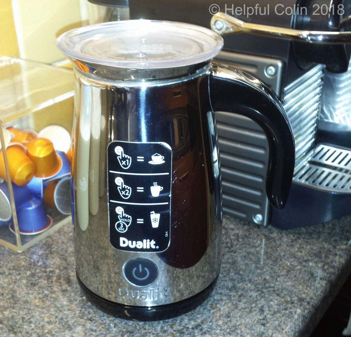
Unfortunately in my haste to buy a replacement and get a bargain I chose to get the model DMF1 which you can see above. It’s black plastic, not silver stainless steel like the original model DMF2, but that’s not a problem. Several of our kitchen items are black or black and silver. I expected it to behave just like the original one.
I knew it didn’t have a pouring spout like the faulty silver one, but thought that wouldn’t be a problem since my original Nespresso Aeroccino didn’t have a spout either. That didn’t have any serious pouring issues.
This turned out to be a BIG mistake. From day one whenever I poured from the Black Dualit Milk Frother and moved from one mug to another the milk ran down the side and dripped off the bottom. The dribbling occurred as I ceased pouring when there was still milk left in the frother. If I poured all the milk into one mug there wasn’t a problem because there wasn’t any milk left to spill at the end of pouring.
The Black Dualit Milk Frother Problem in Detail

When I needed to stop pouring and move onto another mug the curved lip on this new jug wouldn’t break the flow of milk. So, when I straightened up the Dualit Milk Frother it just continued to pour out for a while. The milk ran down the side of the jug and dripped onto the counter or floor. Result:
- the Dualit Milk Frother had to be cleaned,
- the counter had to be cleaned,
- sometimes the floor had to be cleaned.
I had to move the pouring process onto the draining board of the sink, where spilt milk could easily be washed away, in order to reduce the mess.
By comparison the original Silver Stainless Steel Dualit Milk Frother, pictured below, had these benefits:
- a spout shape pressed in the rim,
- the rim had a relatively sharp edge which cut the flow of milk when the jug was tilted upright from the pouring position.

We lived with the new Dualit Milk Frother and its problems for a few weeks, but my wife and I agreed some action was required. So I checked if the heater was still functional on the silver frother and if the internal components of the two frothers are identical. I hoped that if they were I could rebuild the silver frother using the new components from the black plastic one. I removed their Base Plates and found they were more or less built the same. So swapping parts is what I did. The rest of this post describes how I did it.
Take Heed Before Opening A Frother
Safety First!
This post will now discuss a repair to an item which runs from 240 Volt Mains electricity. Because this is a high voltage unsatisfactory repairs can make the item dangerous. So I have included some safety notices:
General Safety Issues
SAFETY DISCLAIMER: I do not take responsibility for anyone who removes even a single screw from their milk frother. The information here is for all to read but only for experts to use.
CAUTION: Anyone attempting to copy this type of repair should have past experience of working on electrical items down to component level. They should also be aware of the laws and safety standards for electrical items with regard to earthing (grounding) and insulation. Failure to be aware could leave an electrical item in a dangerous state, or allow it to become dangerous and a fire risk under fault conditions.
The danger with ignorance is: “Those who know nothing think they know it all.”
Specific Safety Issues
1. When I had opened both Dualit Milk Frothers I observed that there was a basic difference in the wiring. The chrome Dualit Milk Frother had the outer casing and the inner vessel earthed/grounded with interconnecting green and yellow striped earth/ground wires. The black plastic Dualit Milk Frother only has the inner vessel connected to earth/ground since the outer casing is plastic.
2. The black plastic version had the red and black wires for the motor sleeved so they were double insulated. That was not done with the stainless steel version.
Swapping Parts To Repair My Frother
What Items May Require Swapping?
The electronic items which could be damaged and may require swapping between a Silver Stainless Steel Jug and a Black Plastic Jug are listed below:
- the Control Board,
- one or both Thermal Fuses,
- the Temperature Sensor,
- the Whisk Drive Motor,
- the Coaxial Power Connector.
If the Bowl Heater is burnt out the Bowl must be replaced since the heater is welded to it and the Bowls in the silver and plastic jugs are different.
Since there wasn’t anything burnt out on the original and the heater and thermal fuses and motor were OK I presumed the fault was a fault on the Control board and so I swapped it. That turned out to be a good assumption and the repair has been very successful to date.
Dismantling A Dualit Milk Frother
The Silver Stainless Steel Dualit Milk Frother and the Plastic Dualit Milk Frother are similar enough that dismantling them uses the same process. Since I have the parts of the plastic frother available to play with the pictures used in this post are mainly of them.
Gaining Access By Removing The Base
The only way in is through the base which has three Philips screws holding it on. The screws are recessed beneath the white silicon rubber feet which have to be winkled out of holes. A pointed instrument might be required if fingernails aren’t sufficient. Try the tip of a pen-knife blade or a pin. See the two images below:


With the plastic version the screws are self tappers. So I had to be careful not to start a new thread each time I reinserted them. (Too many threads cut in a self tapper’s hole eventually removes so much material that a screw has nothing to bite on.) The stainless steel version has screws tapped with a standard M3 thread.
Observing How The Frother Is Constructed
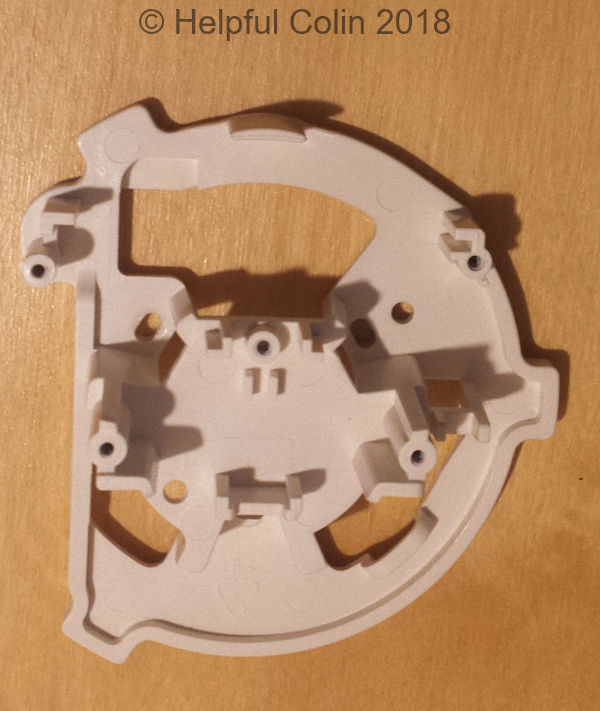
In a plastic Dualit Milk Frother the Bowl is held into the jug by a white plastic part I refer to as the Sub-frame. This part is the same in the silver milk frother but it doesn’t hold the bowl in place. The various parts (e.g. Thermal Fuses, Temperature Sensor, Alignment Fork, etc.) are then either fastened direct to the Bowl or to the Sub-frame. See the Sub-frame below:
NOTE: In order to successfully swap parts from one Dualit Milk Frother to another it’s wise to take photos and make notes about how they are constructed and wired whilst being dismantled. That data can then be used to check they get reassembled correctly. Hopefully my descriptions here will help too.
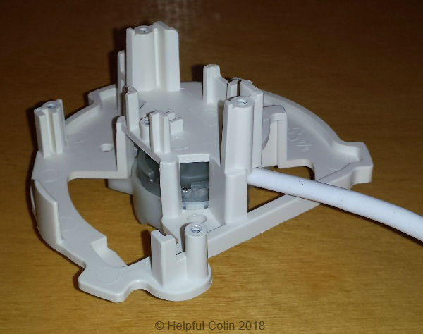
Below both the plastic and stainless steel versions can be seen with their Base Plates removed:


Although it isn’t necessary to dismantle all parts completely I will describe how I think it is best to do it. That will be followed by more detailed description of the parts with pictures showing how some of them fit together with each other. Then I’ll explain how to put them all together to make a working jug.
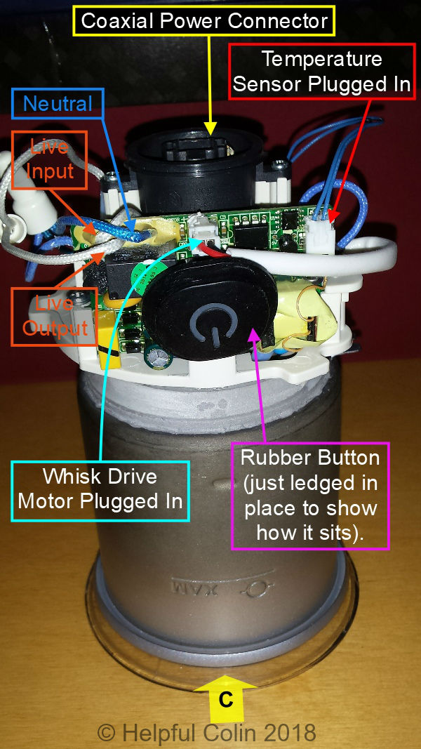
Disconnecting Wires From The Coaxial Power Connector

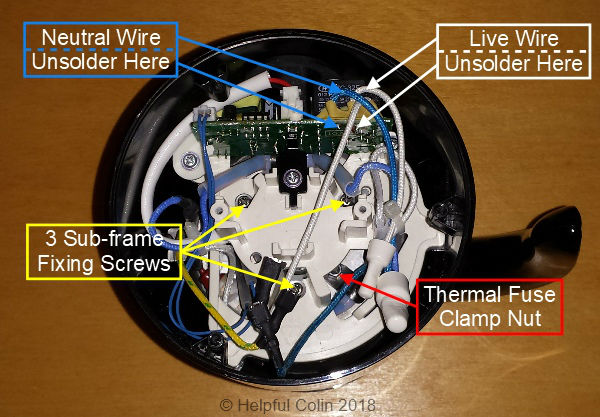
After unscrewing the base the Coaxial Power Connector can be unscrewed from the Sub-frame and lifted away. However it’s constrained by the Live, Neutral and Earth/Ground wires attached to it. These wires are connected to it with spade connectors and must be detached by pulling and wiggling them free.
NOTE: Use of pliers to pull them can easily puncture or rip the insulation. So get your toughest fingers on the job.
The Difficulty With Removing The Sub-frame
Due to their sizes neither the Bowl nor the Sub-frame will pass through the jug body opening at the top. So they have to be separated. The Bowl has to be removed from the top of the jug and the Sub-frame has to be removed from the bottom.
Because the wires connecting the Control Board to the Bowl Heater, via the Thermal Fuses, pass through holes in the Sub-frame the Sub-frame cannot be taken away from the Bowl without disconnecting the wires in some way.
During manufacture two sets of wires from the components are brought together and joined with Closed End Insulated Crimp Connectors. It would be easier to dismantle a Dualit Milk Frother if these crimp connectors were cut off. Indeed that is one option but not the one I chose. New Insulated Crimp Connectors would be required and the wires would get shorter.
Preparing To Remove The Control Board
Refer to: ‘Preparing to remove the Control Board after the Power Connector has been removed.’ above. This will help to disconnect the Control Board and free up the Sub-frame for removal from the jug when following these instructions:
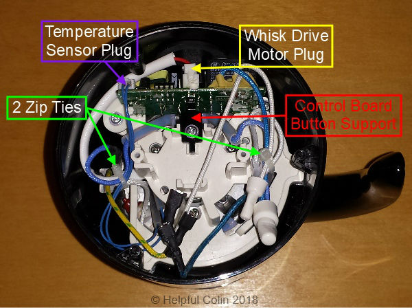
- Carefully cut the two zip ties binding wires together on the left and tying wires to the support post on the right of the Sub-frame.
- Unscrew the screw that holds the Control Board Button Support and remove the support. This support provides a reactionary force (It stops the Control board bending) when the button is pressed.
- Remove the Temperature Sensor Plug from the socket at the top right corner of the board. Don’t pull the wires just grip the small flange around the top of the plug using forefinger and thumb nails and pull it up (or pull it up with small pliers).
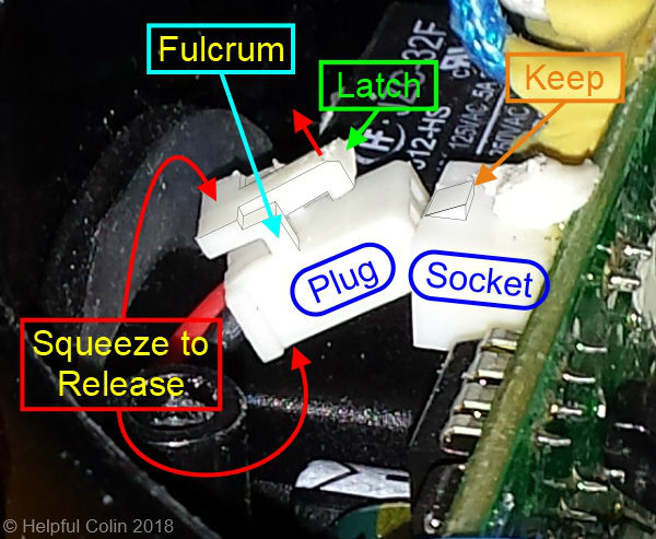
- Remove the white Whisk Drive Motor Plug from the socket at the top middle of the board above the Control Button. This has a little latch holding it in place. The latch must be squeezed against the plug at the point where the wires go in (it has a fulcrum midway) or prised up with a small screwdriver where the latch engages with the keep. It pulls out sideways. If you’re not sure how the catch works get a magnifying glass on the job. See in detail on the disconnected plug below:
Three Methods For Disconnecting The Control Board
At this point there are three methods by which to proceed in order to remove the Control Board and release the Sub-frame:
- Method 1: By cutting off the crimp connectors and replacing them at the time of reassembly. NOTE: This might shorten the wires to the point where they need replacing. Worst scenario is they won’t reach to a satisfactory place where they can be crimped together.
- Method 2: By unsoldering two wires from the Control Board, instead of unclamping the Thermal Fuses from the Heater, it can be completely removed
- Method 3: By unclamping the Thermal Fuses and disconnecting them from the Heater, instead of unsoldering wires from the Control Board, the board can be removed. Unfortunately unclamping the Thermal Fuses is difficult. The Sub-frame must first be unscrewed to loosen it and give access for a box spanner to be used.
Method 1 Starts Here
(Skip Method 1 and go to Method 2)
(Skip Methods 1 & 2 and continue towards Method 3)
Cut Off The Crimp Connectors
There are two blind crimp connectors used within the Dualit Milk Frother. The small one is used for connecting two Live wires and the larger one is used for connecting three Neutral wires. Cut the wires as near to the connector as possible.
Of the two white (Live) wires:
- one goes to the Control Board Relay Contact,
- the other goes to a Thermal Fuse.
Of the three blue (Neutral) wires:
- one supplies a Neutral Feed to the Control Board,
- one goes to a Thermal Fuse,
- the other connects to the Neutral Tag on the Coaxial Power Connector.
Method 1 Ends Here
Method 2 Starts Here
(Skip Method 2 and continue after Method 1, or continue to Method 3)
Unsoldering Some Wires From The Control Board
Refer to: ‘Preparing the Sub-frame for removal.’ above when following these instructions:
- A Latex type substance holds the wires to the Control board. It has to be stretched until it comes away from the wire insulation.
- Unsolder the Blue Wire from the Control Board. This is the Neutral supply to the board.
- Unsolder the White Wire which connects to another White Wire at the Crimp Connector which comes from a Thermal Fuse. This is the Live connection to the Heater fed via the Relay Contact.
Method 2 Ends Here
The Following Applies To All Methods
Removing The Control Board

Refer to: ‘The Control Board clamped in place.’ and ‘Releasing the Control Board.’ above when following these instructions:
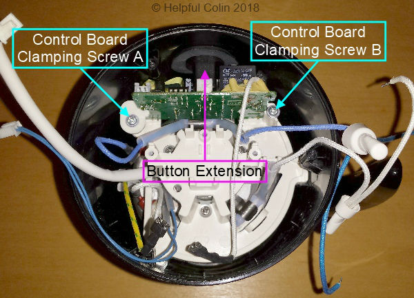
- Remove Clamping Screw A and the Control Board Clamp it holds.
- Loosen by 2 turns (but don’t remove) Clamping Screw B to free up the Control Board.

Refer to: ‘Pulling the Control Board out of place.’ above when following this instruction:
- Pull the Control Board back and up out of its slots in the Sub-frame. There may be difficulty getting the Control Button LED (light) past the rubber Control Button’s Plastic Extension.
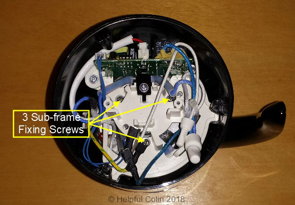
Refer to: ‘Releasing the Sub-frame by removing the three Fixing Screws.’ above when following this instruction:
- Remove the three screws holding the Sub-frame in place. These each have a split washer and a plain washer on them. NOTE: the split washers go next to the screw head. They can be ferromagnetic and stick to the Whisk Drive Motor Magnets if dropped into the jug. The Whisk Drive Motor will remain attached to the Sub-frame by three plastic catches.
Method 3 Starts Here
(Skip Method 3 if using Method 1 or 2)
I originally dismantled my Dualit Milk Frothers using this method. It was only when I considered how difficult it would be to reverse the process, in order to reassemble them, that I unsoldered the two wires from the Control Board and devised Method 2.
Unclamping Thermal Fuses From The Heater
- Remove both spade connectors from the tags on the end of the Heater by pulling them upwards.
- Use a box spanner, or similar tool, to loosen the nuts on the studs holding the Thermal Fuse Clamps so that they become loose and free the fuses. The nuts become accessible through the holes in the loose Sub-frame. Move the Sub-frame around to access the nuts.
- As the Control Board comes out it will pull out the two Thermal Fuses and their wires. They may snag on their way out and need attention to keep them free. Observe how these wires are threaded. That knowledge is needed for re-assembly.
NOTE: I consider this method flawed because of the difficulty of mounting the Thermal Fuses in the confined space when reassembling the frother.
Method 3 Ends Here
The Following Applies To All Methods
Removing The Sub-frame
With the jug upside down on a bench (above) and the three screws, which fix it to the bottom of the bowl, removed the Sub-frame can be rotated anticlockwise (below) and lifted out of the jug with the Whisk Drive Motor still attached to it. The motor shroud has catches which clip onto the Sub-frame. By rotating the Sub-frame anticlockwise the lugs and Control Button Extension avoid the projections on the inside of the jug when it’s lifted out.

If wires have been cut (using Method 1) or unsoldered from the Control Board (using Method 2) the Thermal Fuses will remain attached to the Bowl and the wires will pull through the holes in the Sub-frame. Else the free Thermal Fuses (released using Method 3) will lift off the Bowl and come out with the Control Board and Sub-frame combination.
NOTE: It’s the threading of the wires through the holes in the Sub-frame that should be noted for satisfactory reassembly. Take photos.
In the case of the plastic jug the Lugs on the Sub-frame could be numbered, with an indelible ink pen, to agree with the labels on my images in this post. Observe how those Lugs bear down on the Mounts protruding from the Jug Body and how the Alignment Fork engages with the Alignment Rib. Observe how the Mount near the jug handle has projections on the sides to hold the lug and prevent the Sub-frame (and so the bowl) rotating.
Differences with The Stainless Steel Jug
With the stainless steel jug the lugs don’t play any part. The bowl is pressed into the jug so the lugs aren’t required to hold it in and the splines prevent it rotating. The splines also make a good earth/ground connection between the two components.
Move The Motor & Sub-frame To Another Jug
If necessary the Whisk Drive Motor can be removed from the Sub-frame by prising at the catches with a small thin bladed screwdriver or knife. However a good Whisk Drive Motor can be moved to another jug by transferring the whole Sub-frame complete with motor. See the example below.
Removing The Bowl
The Plastic Jug Body should easily separate from the Bowl at this stage by holding the Bowl down and lifting the Jug Body off the top rim of the Bowl.
The Stainless Steel Jug cannot be separated form the Bowl because of the way they are pressed together.
The Parts Of A Dualit Milk Frother
After dismantling the Dualit Milk Frother I had a selection of parts spread over the workbench. This section describes them all in some detail.
Parts For The Plastic Jug
The Plastic Jug Body
The Plastic Jug Body (below) has a synthetic rubber button mounted in a hole in the side. This doesn’t have to be removed for any reason other than to replace it if it were damaged. Interestingly it isn’t the same shape as the similar part in the stainless steel jug. In the plastic jug the rubber button and its hole are oval, but in the stainless steel jug they are circular. These buttons are held by a groove in the rubber whose flanges wrap around the edge of the hole like a grommet would.

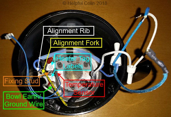
There are twelve ribs inside the Jug Body set at 30° intervals. The one opposite the handle (the Alignment Rib) is larger than the others and engages with the Alignment Fork fixed to the Bowl on a stud with the Ground Wire.
It’s easy to locate the three mountings, inline with ribs which are 120° apart, for the Base Plate Screws. NOTE: The one near Sub-frame lug mount 2 is at a different level to the other two. This ensures there is only one way to fit the Base Plate.
There are three bearings, numbered by me, protruding from the inside about 3cm further into the jug towards the top. These are inline with the Base Plate screw mountings. These bearings are for the Sub-frame Lugs, to which I have given the same numbers. They take the pressure when clamping the Bowl in place.
The Bowl And Its Construction

The Bowl (see the side view above & underneath view below) is a cylinder with an open end at the top to put the milk in and a closed end at the bottom with a 230V/500W Heater fused to it. The circular heater has two spade connector tags at its ends spaced 2cm (30°) apart.
The Bowl’s made of non-ferromagnetic metal so that the magnetic field from the eight Whisk Drive Magnets can pass through it. On the outside the four drive magnets attached to the motor shaft can be positioned near to and underneath the bowl in the Magnetic Drive Zone, and on the inside the four whisk magnets get near the bowl bottom when the domed end of the whisk spindle rests on the bowl. This allows them to be magnetically coupled so the motor can drive the whisk.

Underneath the bowl there is also a Temperature Sensor to measure the milk temperature and give feedback allowing the heat to be controlled.
A short green and yellow wire with a spade connector connects the body of the bowl to the incoming ground connection at the centre of the Coaxial Power Connector.
Mounting The Bowl
The bowl also has three threaded mounting points for the Sub-frame and Whisk Drive Motor to be firmly fixed. The bowl is mounted through the top of the jug with its lip over the jug’s edge. Then, when the Sub-frame is fixed in place, three lugs on its outer edge bear on mounts on the inside of the jug wall so that the jug body is sandwiched between the Sub-frame and the lip overhanging the top of the jug. The Whisk Drive Motor is also held in position beneath the Bowl by the Sub-frame and the same three screws.
Parts For The Silver Stainless Steel Jug
The Steel Body
Below is a picture of the silver stainless steel jug with the Base Plate removed. The base fixing lugs and supports are all part of a steel ring welded (or otherwise fixed) inside the jug body.
On the left loose wires are tied together with a zip tie and on the right a zip tie holds them to an anchoring point on the Sub-frame.
The Bowl
I would say the Bowl is pressed into the jug body since there are signs of splines where it fits into the top edge of the jug. I suspect it cannot be removed and that the Sub-frame doesn’t play any part in securing it.
Parts Common To Both Types of Jug
The Base Plate
The Base Plate (above) is a simple disk of plastic with a 32mm hole in the centre to give access to the Coaxial Power Connector. It also has three screw holes so it can be held onto the jug body and six drain holes to let liquids escape, and let air circulate.
The Base Plate is shown here with the Coaxial Power Connector sitting in its normal position relative to the location of the Jug Handle and Control Button. The connector doesn’t get directly fixed to the Base Plate. It fixes to the Sub-frame.
There is a slight difference between the chrome and plastic jugs:
- The Chrome Jug Base Plate is held on by three M3 Philips screws,
- The Plastic Jug Base Plate is held on by three self-tapping Philips screws.
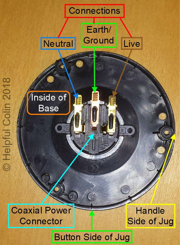
The Coaxial Power Connector

The Coaxial Power Connector (above) fixes onto the Sub-frame with two self tapping Philips screws. When the Base Plate is finally fixed to the jug the central hole engages a flange on the Coaxial Power Connector. It has three spade connections Live, Neutral and Ground.
The Ground Connection has a Green and Yellow Wire connecting it to a stud on the Bowl which also holds the two pronged fork used on the plastic jug. The fork engages a fin moulded on the inside of the jug body opposite the handle. This arrangement ensures that the bowl and all attached to it keep the correct orientation within the jug.
The Live connection has a White Wire connecting it to the Control Board, to give it power, and to one side of the relay contact. The other side of the relay contact connects, using white wires, to one of the 257°C Thermal Fuses via a (2-wire) Crimped Connector.
The Neutral connection has a Blue Wire connecting it to the Control Board, to give it a return path for the power, and the other 257°C Thermal Fuse via a (3-wire) Crimped Connector.
The other ends of both thermal fuses connect to the 230V/500W Heater Spade Terminals.
All white and blue wires so far mentioned and the thermal fuses are covered with heat resistant insulation.
The Dualit Milk Frother Base
The coaxial nature of the power connector is more apparent when the Dualit Milk Frother Base on which the jug rests is observed (see below). This is the normal view of the base with the Guard Ring closed. Only the Earth/Ground connection (which is safe) is exposed. The Live and Neutral connections are concealed.

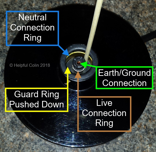
The picture above has the guard ring pushed down by a wooden stick as would be the case when the jug rests on it. This exposes the Live and Neutral connections, which are in the form of concentric brass rings, so that the contacts on the Coaxial Power Connector can make connection. Having circular connection rings allows the jug to maintain an electrical connection at all angles.
The Sub-frame
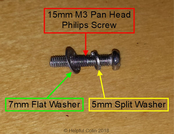
The Sub-frame (below) is a white plastic moulding which fixes underneath the Bowl with the same three 15mm M3 pan head screws which firmly hold the Whisk Drive Motor in place. When the Sub-frame is fixed in the plastic jug the Bowl is held in place too.
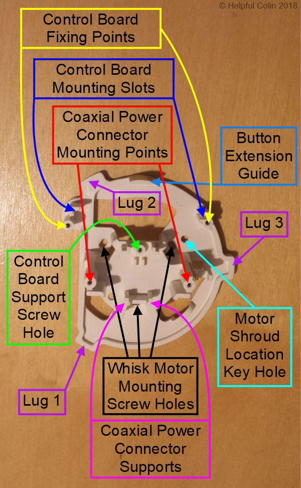
The Sub-frame also has mounting points and supports for the:
- Whisk Drive Motor,
- Coaxial Power Connector,
- Control Board,
- Control Board Support.
It also has large holes giving access to parts and interconnecting wires.
The diagram below is a cross section of the Jug Body, Bowl and Heater with the Sub-frame and Whisk Drive Motor attached. It demonstrates how the Bowl is held into the plastic jug. The Bowl lip is pulled down onto the top edge of the jug when the three fixing screws holding the Sub-frame onto the Bowl are tightened. The three lugs on the Sub-frame push up against the bearing points moulded onto the inside of the Jug Body, and so the jug is gripped between the Bowl and the Sub-frame.

The Whisk Drive Motor

The Whisk Drive Motor (above) is shown from the back where the wires attach to the brushes.
As far as I can tell this is a 10.5V D.C. motor. How do I Know? I guessed it from the 10.5V printed in big digits on the back of the Control Board. I tried running it from a 10.5V D.C. supply and it ran at the normal speed I see the whisk going round at. This one has double insulated wires (red & black) in a white sheath about 13cm long terminating in a miniature 2 pin plug. The socket for this plug is on the Control Board adjacent to the Control Button.
Below is the other end of the motor, the business end. This has a 22mm dia. rotor holding four square magnets in a cross formation. Their visible face polarity’s are North, South, North, South, on a 13mm dia. pitch circle. The whisk has similar magnets embedded in it. So the whisk on the inside of the bowl remains aligned with the motor on the outside because the Norths on one are attracted to the Souths on the other. This magnetic bond keeps them pulled as close to each other as possible, so forcing the whisk to rotate in sync with the motor.

The Whisk Drive Motor Shroud
Potentially there are three ways in which the motor shroud could be fixed in place due to the three screw holes being 120° apart but, due to the Location Key adjacent to one hole it can in fact only be assembled one way.
See the Location Key in the images of the motor. This fits into a Location Key-hole in the Sub-frame.
The plastic shroud on the motor has three catches located at each screw hole. Each has a sloping face. These catches engage with the Sub-frame such that once clicked together they won’t separate. I had to prise each catch with a thin bladed screwdriver to dismantle the motor from the Sub-frame. See the Catches in the image of the motor below.
How The Shroud Fixes To The Sub-frame
The image above gives a view of one of the Catches on the Motor Shroud which fixes it to the Sub-frame. It also shows where the Location Key is situated. This is the back of the key, not its protruding side.
Below is a larger image of two of the three Fixing Catches. From this image their shape is clearer. They are designed to go past their three mounting points by forcing them apart and then the mounting points spring together behind the catches thus retaining the motor by its shroud.

The Whisk

The whisk can be seen in a plastic jug above. The rotating part (the whisk proper) is encircled, as is the MIN (minimum) height of milk marker. The large diameter circular grey plastic framework just supports the rotating whisk on a steel spindle and does not itself rotate. In fact there are protrusions moulded on it which cannot get past protrusions on the inside of the jug if it tries to rotate.
Rotation of the whisk stirs the milk so that the heat is evenly distributed. If it remained still the milk would burn onto the bottom of the bowl. The whisk does, of course, froth the milk but only when it goes fast. See the following whisk control data.
Whisk Control is done by the number of button presses (about 1 per second) thus:
- One press = Hot frothy milk and a steady red light using a fast whisk.
- Two presses = Hot milk with no froth and a flashing red light using a slow whisk.
- Three presses = Cold frothy milk and a steady blue light using a fast whisk.
Check out the illumination of the Rubber Button here.
The upturned whisk is shown below where the rotating part (the whisk proper) is encircled. It’s the action of the circular spiral wire spring ,agitating the milk as it rotates, which froths the milk.

The Control Board

The Control Board (above) allows the user to turn on the 500W Heater attached to the bottom of the bowl to heat milk and at the same time switch on the motor to drive the whisk fast or slow.
Operating The Control Button
The user follows the instructions provided by the manufacturer and presses a rubber button to effect control. The rubber button presses on the Control Button Plastic Extension which in turn presses on the Control Button shown on the board. The LED Button Light which glows within the rubber button is mounted just below the Control Button on the board and shines through the tubular hole in the Extension. See, “The Rubber Button & Plastic Extension.”
Correct assembly of the rubber button in its location hole in the side of the jug body when the board is inserted allows the light to shine correctly through the translucent part of the rubber button.
Attaching Peripherals To The Control Board
Above the Control Button is the Whisk Motor Socket where the red and black wires from the motor connect.
The Temperature Sensor, with its two blue wires, connects to a similar, but physically different, socket at the top right corner of the board.
The Power Relay has one contact which is wired in series with the mains power so that it can switch power ON and OFF for the 500W Heater under the Bowl.
In the Control Board picture the AC Power Out wires have been unsoldered from the Control Board (as in Method 2). They go into the board from the top where you can see two black holes in the rubber stuck to the board. AC Power In shares one of these (Blue) wires. The two wires which get connected together by the relay contact are white. They can be seen on the Control Board Wiring picture below.
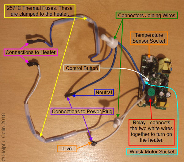
The Control Board Wiring picture (above) and the Schematic Diagram below, show how the 257°C Thermal Fuses are connected.

Those fuses are physically clamped to the heater so that they can get hot when it gets hot. If it gets too hot those fuses will break the connection to the heater so that it will cool down. These fuses should only blow under severe adverse overheating conditions and are there for safety’s sake to prevent a fire starting. If those fuses do go open circuit the jug would require repairing by an electrician. The cause of such a failure might bring the jug to the end of its life because the cost of repair may be too high.
The Rubber Button & Plastic Extension
The Rubber Button
See the large Black Rubber Button below is from a plastic jug. It’s made like a rubber grommet with two flanges separated by a groove. The flange on the inside is larger than the outer flange suggesting the button should be inserted from the inside.
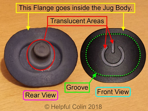
The groove has a small obstruction moulded into it at top centre. This matches the small notch cut in the top centre of the Jug Body Hole and acts as a keyway to ensure the button is mounted the right way up.
NOTE: The Rubber Button of the Silver Stainless Steel Frother is circular not oval like this one from a Black Plastic Frother.
The Rubber Button Lighting
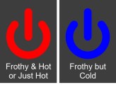
The Power Symbol (above) moulded in the Rubber Button is translucent. So it emits light shone on it from the inside by the Blue/Red LED mounted on the Control Board. The three conditions presented by the light, according to the number of button presses, are:
- Steady RED = Frothy and Hot milk,
- Flashing RED = Hot milk only,
- Steady BLUE = Frothy but Cold milk.
The Plastic Extension
The Control Button, mounted on the Control Board, is very small and has to be connected mechanically to the large Rubber Button on the side of the Jug Body so it can be operated by the user. This is achieved using a Hollow Plastic Extension which mounts on the back of the Rubber Button. See below:
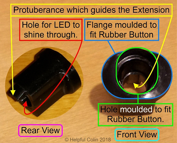
With the extension being hollow the Blue/Red LED, mounted immediately below the Control Button on the board, can shine through and onto the translucent part of the rubber so it can be seen on the outside.

How The Extension Engages With The Push Button Switch
Above: The Plastic Extension can be seen fitted into the Rubber Button so it is moved when the button is pressed. It has a small protuberance on the Control Button end which helps to guide the extension by sliding underneath the LED mount fitted on the Control Board. Thus when the Rubber Button is pressed the Control Button gets operated by the top edge of the Plastic Extension pressing against it.
The workings of the Control Button Extension and its interaction with the Control Button and Blue/Red LED are shown in the two cross-section diagrams below. The top image shows the push-button switch in the released state and the bottom image shows the push-button switch operated when the rubber button is pressed.
NOTE: The Blue/Red LED sits inside the Control Button Extension.

Reassembling The Dualit Milk Frother
In order to try and show the assembly process clearly I will show how the parts are assembled outside the jug body so that they can be clearly seen without the Jug Body in the way. Then I will assemble it inside the Jug Body to give a view of the real situation and let you see the tight conditions in which the parts sit.
Assembling The Parts Outside The Jug Body
Attaching The Whisk Drive Motor To The Sub-frame
Below is the inverted Sub-frame with the Whisk Drive Motor pressed into position from underneath. The motor is held to the Sub-frame by three small catches until it is screwed to the Bowl.
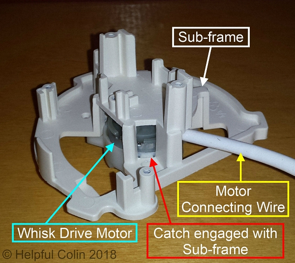
This attitude is the one seen when the Sub-frame is mounted on the inverted Bowl within the Jug Body as it is assembled upside down on the workbench.
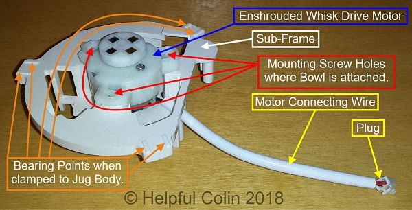
Below we can see the Whisk Drive Motor mounted on the Sub-frame from the other side. The Bowl sits on top of this in its normal attitude. The three threaded posts mounted on the bottom of the Bowl sit in the recesses around the screw holes in the Motor Shroud.
Clamping The Thermal Fuses To The Bowl Heater
Below you can see I have clamped the Thermal Fuses to the Heater on the bottom of the Bowl. The nut can be tightened with a 5.5mm, 7/64″ or 5BA socket. I have then connected one end of each fuse to a Heater Terminal using The Spade Connectors.

In my case I have unsoldered the Blue and White wires, which link to the fuses, from the Control Board (see Method 2). I did this to make it easier to dismantle and reassemble the Dualit Milk Frother. The wire insulation is also glued to the board. This adds to the difficulty of unsoldering the wires.
I suspect the manufacturer built it with a wire from each fuse, a Blue and White wire from the Control Board and a Blue wire from the Coaxial Connector. Then after all parts were fixed in place the three Blue Wires were joined in one crimp connector and the two White Wires were joined in the other. To reassemble it with those wires already joined in the Crimp Connectors is no easy feat.
Securing The Control Board
Below is the Control Board fixed to The Sub-frame with two Pan Washer Head Screws. One screw just bites the edge of a notch in the board. The other holds the board in place with the aid of a shaped piece of plastic which fits into a notch in the board.
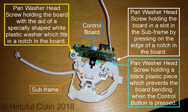
The board is shown without any of the associated wiring just to give a clear view of how it is assembled.
Behind the Control Button a black plastic support is mounted to take the pressure when the button is pressed.
Threading Wires Through The Sub-frame & Fixing It To The Bowl
It’s only at this stage that it becomes obvious which holes in the Sub-frame to thread the various wires through.
Below is a picture of the Sub-frame, with the Whisk Drive Motor and Control Board attached, after it has been screwed onto the bottom of the Bowl. Observe how the Live, Neutral and Temperature Sensor wires are threaded through the Sub-frame from this.

The Sub-frame is held to the bowl by three M3 Philips Pan Head 15mm screws, each with a split washer and 7mm dia. flat washer. The flat washers help spread the load over the elongated Sub-frame holes. NOTE: The manufacturer has used enough torque to dent the plastic of the Sub-frame and flair the flat washers slightly and give them a conical shape
When the Sub-frame is fixed in place it isn’t possible to use a box spanner or socket on the nuts holding the Thermal Fuse Clips in place. The Whisk Drive Motor Rotor gets in the way. During the dismantling process it’s easy to release the Sub-frame so it can be moved (still not easy in the confines of the Jug Body) to give access. The difficulty with reassembly is in holding the Thermal Fuses in place while their clips are tightened. There just isn’t the space in the confines of the Jug Body to get parts, tools and finger in all at once and do a neat job.
This is why the manufacturer has mounted all the parts and then joined wires with insulated crimped connectors. To repair the Dualit Milk Frother the connectors could be cut off and replaced. I hadn’t got any suitable connectors so I opted to unsolder two wires from the Control Board instead (see Method 2).
Fixing The Coaxial Power Connector To The Sub-frame
Below is a picture of the completed assembly with the Coaxial Power Connector fitted and wired up.
The two wires which I originally unsoldered to facilitate disassembly and reassembly have been soldered back onto the Control Board.
The Temperature Sensor and Whisk Drive Motor wires have been plugged back into the sockets on the Control Board too.
The wire referred to as Live Input is the Live Connection from the Coaxial Power Connector to the Control Board. Live Output is the connection from the Control Board to the Heater via the inline Thermal Fuse.

I have taken photos of the final assembly from four sides A, B, C & D as indicated by the broad arrows labelled A to D on the above picture. Those four images labelled A to D are displayed below.


The Thermal Fuses have considerable translucent insulated heat resistant sleeving on them. In the case of the Thermal Fuse inline with the Live wire its wire is bent vertical to project through a hole in the Sub-frame near to where the Insulated Crimp Connectors are held. See view in direction ‘D’.
The two ends of the Neutral Thermal Fuse both project up through the same hole in the Sub-frame behind the Control Board.
I hope these images show sufficient detail for any technician repairing a Dualit Milk Frother to be able to get the wiring straight during reassembly.
Assembling The Parts Within The Jug
The following assembly instructions are for a frother dismantled by Method 2 where two wires are unsoldered from the Control Board.
1. Start With The Jug Body
Above: The inverted Jug Body with the Handle to the right. The Rubber Button has been inserted in its hole in the side. Since it has a large inner flange and a smaller outer flange the Rubber Button should be pushed, squashed and stretched into place from the inside of the jug.
This image also shows the three Sub-frame Lug mounts where the Lugs engage to hold the bowl in place. Note that Mount 3 is different to the other two. It has side pieces not easily seen because of the dark colour. These sides can be felt and project towards the bottom of the jug. Their purpose is to engage Lug 3 and prevent the Sub-frame from rotating and becoming displaced.
NOTE: There aren’t any Lug Mounts on the Silver Stainless Steel jug. The Bowl is held in place by being pressed into the Jug Body which it grips with splines on its top edge.
Also visible are the three mounts for the Base Plate self tapping screws. Note that the one near Sub-frame Lug Mount 2 is 1cm from the bottom of the jug and the other two at 1.6cm from the bottom. If nothing else this ensures the Base Plate can only be attached in one position.
2. Insert The Bowl
If this were a Stainless Steel Jug there would be no insertion of the Bowl due to the Bowl’s permanent style.
Below: The Bowl can be seen inserted into the plastic jug. If an exchange of parts is taking place then the components seen in this image may never have been removed from the bowl. However fitting these components to the bowl before inserting it can make the job easier.
NOTE: When it comes to connecting the Thermal fuses to the Heater the connection tags on the Bowl heater are labelled (L) Live & (N) Neutral.
There is a stud mounted in the Bowl upon which are fixed the following three items held by an M3 nut and star washer:
- Thermal Sensor,
- Alignment Fork,
- Earth/Ground Wire for the Bowl.
These are best fitted before insertion of the bowl as it is important that the Alignment Fork is engaged with the Alignment Rib so that the Bowl to get it correctly oriented. This alignment must be carefully made as the bowl is inserted.
At this point the plastic bowl isn’t held in by anything. The top edge of the jug is just resting on the lip of the bowl.
3. Insert The Sub-frame
In preparation the right hand Control Board Clamping Screw should be inserted about half way. This reduces the chance of the screw being accidentally dropped into the jug later.
During this procedure the Whisk Drive Magnets need to be facing down towards the Bowl.

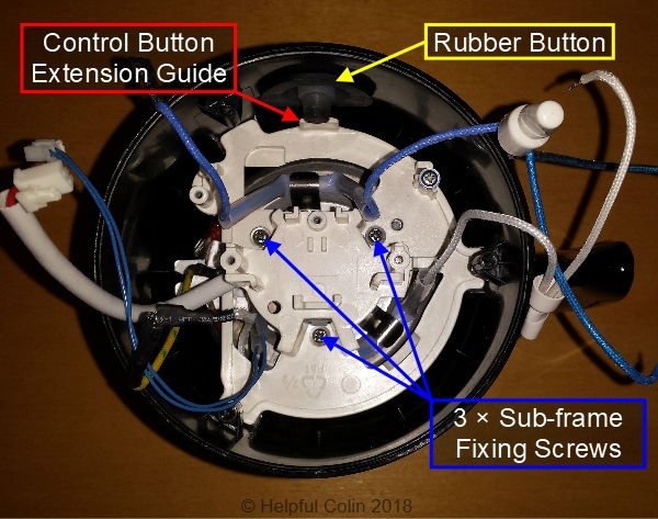
Refer to the image above and lower the Sub-frame into the jug through the open base, a few degrees anticlockwise of its normal position, so that the Control Button Extension Guide appears to be on the left of the Rubber Button. By doing this the Mounting Lugs will pass by the Base Screw Mounts.
At the same time as lowering the Sub-frame into the jug various wires must be threaded through the holes in it as follows:
- Hole X: Wires on both ends of the Neutral Thermal Fuse, i.e. The wire that plugs onto the Neutral Heater tag and the Neutral wire with the insulated crimp connector attached together with the other two wires joined by it.
- Hole Y: The Live wire from the Live Thermal Fuse which goes to the other insulated crimp connector together with the other wire joined by it.
- Hole Z: The Live wire from the Live Thermal Fuse which plugs onto the Live Heater tag. Also the two wires from the Temperature Sensor.
NOTE: The insulation on the Blue and White Neutral and Live wires is made of a woven material coated with a synthetic (probably silicon rubber) skin. This skin can be damaged by the sharp edge of the Sub-frame plastic as the wires are dragged through the holes.
4. Twist The Sub-frame Clockwise & Fix It In Place
When the Sub-frame is just above its mounts twist it clockwise a few degrees to align the Lugs with the Mounts. This will also move the Control Button Extension Guide in front of the Rubber Button. See the image below.
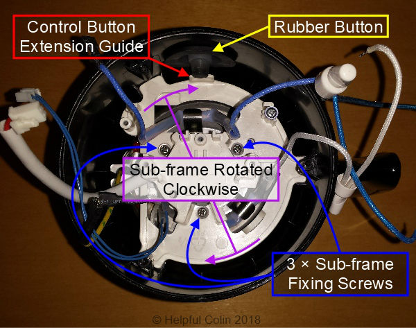
When the Sub-frame is in position the three fixing screws, complete with washers, can be inserted and tightened. The Bowl will then be firmly fixed in place. The correct position will have the plane of the Control Board mounted at right angles to a line passing through the centre of the Rubber Button.
5. Insert The Control Button Extension
Note how the Control Button Extension should be positioned and fit it into the Rubber Button. Let it rest on the Control Button Extension Guide and fiddle it into position as the Control Board is inserted.

6. Install The Control Board
The three pictures below show the Control Board being put into the slot on the right (next to clamping point B). Then the left edge is coerced into position with:
- a push to the right,
- a push downwards,
- and then a push forward.
Once the Control Board is in position Clamp A can be applied and Clamp B screw can be tightened. The three images below run through the sequence.


At this stage the Control Board button Support can be fitted to the centre of the Sub-frame with one Pan Washer Head Screw. It has a slot and guides to align it and keep it straight. Note how it tilts towards the base where it touches the Control Board. See the image below.
Then the two plugs for the Temperature Sensor and the Whisk Drive Motor can be inserted into their respective sockets. See the image above.
7. Soldering The Wires Onto The Control Board
The image below shows the Blue Neutral Wire and the White Live Wire which feeds the Bowl Heater after they have been soldered in place. To re-solder these wires they need to be tinned straight at the tip and without strands of wire sticking out sideways.
The holes on the Control Board need to be cleared of old solder so that the wires can easily be pushed through before soldering. This can be tricky. Those who have done plenty of soldering to repair circuit boards will probably be used to dealing with this situation. There are tools called Solder Suckers which can be used to heat solder and then suck it off the board. I find an old darning needle (the rustier the better so solder won’t adhere to it) useful to poke in the hole when heated. This can make the solder pile up on the copper strip away from the hole. Large amounts of solder can be gathered onto the iron tip using gravity and taken from the board. The solder is then cleaned off the iron.

Finally the wires can be formed neatly and tied in a bundle or to the plastic support on the Sub-frame with zip-ties to stop them floating around. This action should leave the three spade connectors which connect to the Coaxial Power Connector in the right location.
8. Attach The Coaxial Power Connector
The Coaxial Power Connector mounts on top of the Sub-frame (when upside down) and is fixed in place with two 10mm × 3mm self tapping Philips screws. Three spade connected wires must then be plugged onto the tags – Neutral, Ground/Earth and Live as listed and shown in the image below:
- Neutral = Blue,
- Earth/Ground = Yellow with a Green stripe IN THE CENTRE,
- Live = White.
9. Fix The Base Plate On The Bottom of The Jug
The Base Plate has to be oriented, as shown below, with respect to the jug handle because one screw is in a shallow hole and the other two are in deep holes. The Base Plate is held in place with three 10mm × 3mm self tapping Philips screws.
When the screws are tight they are covered by inserting the silicon rubber feet in the same recesses. See below:

10. Test The Dualit Milk Frother
All that is left to do is to test the Dualit Milk Frother to check it works OK. Be aware this is when it might not work. So be ready to deal with any problems that could arise.
CAUTION: In the event of a serious problem there could be undue noise, burning, smell, smoke, etc.. Be ready to disconnect at the mains plug if any of these things occur, before taking any other action to extinguish fire.
Possible Corrosion In A Dualit Milk Frother?
See my Blog Post: Is My Dualit Model DMF2 Milk Frother Corroding?
Leave a Reply