Introduction
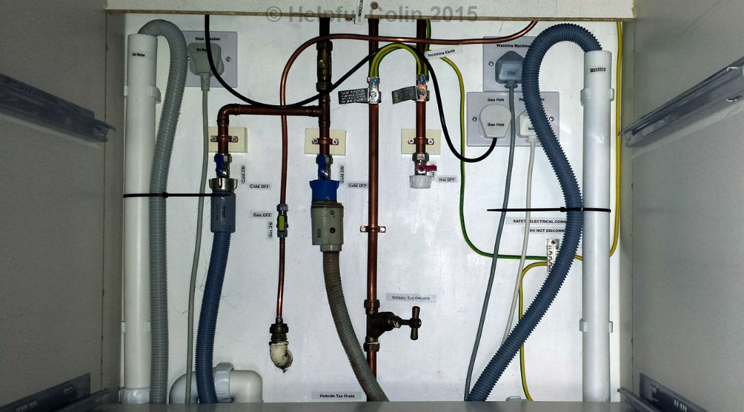
Everyone has to design their kitchen or utility room to suite their circumstances but when my kitchen came up for renewal in 2003 I made specific use of the considerable space behind my pan drawers. I discarded my pan drawer carcase back panel and brought together many of my kitchen appliance connection points onto this large area of wall space behind the drawers, as shown in the featured image.
My Old Kitchen Appliance Connection Points
Prior to this kitchen I only had a washing machine (no dishwasher or tumble dryer) and the taps for that were mounted on the wall inside the sink cupboard. The washing machine was adjacent to the sink under the worktop but in a space larger than 600mm. All the extra space (about 70mm) was designed into this location to give extra room for manoeuvring a washing machine. It also allowed me to fit a standing drain pipe in the back corner near the sink cupboard and a power socket on the wall directly behind the machine. That socket was fed from a switched fused spur above the worktop.

The carcases of my previous kitchen had chipboard side panels that reached down to the floor (a big mistake not repeated in modern kitchens which have adjustable legs instead). It meant access for cables and pipes between units required holes and cut-outs to be made in the carcase sides. Also the chipboard could get wet whenever there was flooding from faulty appliances, and as we all know water and chipboard1 don’t mix. However the chipboard edge of those carcases didn’t rest directly on the floor. There were some studs in the edge giving a 4-5mm gap and I glued strips of 4mm thick ramin wood to the floor to spread the weight of the units from those studs so that they didn’t sink into the asphalt floor over time.
“I once lost a comb in a washing machine. It went down between the inner drum and the rubber door seal into the outer drum. At some point in the inner drum’s rotation it jammed between the outer surface of the inner drum and a plastic bung mounted in a hole at the back of the outer drum. The teeth were ripped off half of the comb as its spine was forced through the bung allowing all the water to be drained onto the floor immediately. That amount of water can soak into chipboard (even when it’s melamine coated) and ruin a good unit before the washer can be moved out of the way.” — HC
An Alternative Appliance Waste Connection

For this type of waste to be used provision has to be made for the appliance waste hose to be taken into the cupboard under the sink. That could require a hole cut in the side or the back of the cupboard. If the appliance water stop tap is also mounted on the wall at the back of the sink cupboard the waste hose might come through the same access hole cut in the back panel.
There are waste-pipes for kitchen sinks which have sockets on them to which the flexible pipes of washers can be directly attached. Here for example is a FloPlast Sink & Washing Machine Trap which has a washer drain pipe inlet between the waste and the sink. (I hope water doesn’t flow from the sink and drain into the washing machine.) Connected this way the one trap works for both sink and appliance.
Attaching pipes in cupboards can take up space in the cupboard and break up the shape of the space making it more awkward to store things, and if there are any water leaks items stored can get wet and dirty as can shelves and the carcase. Again this can lead to a wet chipboard1 issue. Melamine coated shelves in particular can get damaged when water runs to the ends where the chipboard is usually exposed. The same happens to the ends of the bottom of a carcase where it butts up against the sides. Capillarity wicks the water into these areas. If it goes unnoticed for a few hours expensive kitchen cupboards can be ruined very quickly.
My New Kitchen Appliance Connection Points
Once the decision was made to have a washing machine and a dishwasher (i.e. two appliances requiring water, power and waste outlets) I knew I would have to cater for at least one of them in a special way (i.e. one would have to be away from the sink). This is what made me think how I might move them anywhere along the line of units along the main wall of my kitchen by extending the main drain and water pipes for the sink. Realising I needed plenty of space for all the kitchen appliance connection points involved I found all the issues could be resolved if I put the appliances either side of my hob and placed that over pan drawers instead of a cupboard.
I didn’t have to make provision for a tumble dryer because that is not in the kitchen.
Incorporating Pan Drawers In A Kitchen Layout
Cooking pans are large bulky items that need plenty of storage space. Consequently a lot of people build Pan Drawers into their kitchens especially to store them. Pan drawers can be conveniently placed under the area of worktop occupied by the hob. (After all, that is where they’re needed.) Hobs protrude beneath the worktop and might interfere with small drawers for cutlery and the like, especially if they are hobs over 600mm wide, but pan drawers are deep and can have low backs which prevents them making contact with the underside of a hob when they are opened. Obviously the contents must not engage the underside of a hob either. Alternatively hobs are placed over cupboards or low level ovens.
At the end of the day everyone has to design their kitchen drawers and cupboards to fit into the space available. I found pan drawers, being 800mm wide, enabled my units to fit very well between the walls at opposite ends of the room to create a ‘galley style’ kitchen.
In order from left to right I have the following base units, etc.:
- full height built-in oven unit – 600mm,
- sink unit – 1,000mm,
- 3 drawer unit – 600mm,
- built-in dishwasher – 600mm,
- pan drawers – 800mm,
- built-in washing machine – 600mm,
- full height built-in fridge-freezer – 600mm,
- full height filler strip – 20mm.
Total length of base units + filler strip = 4,820mm.
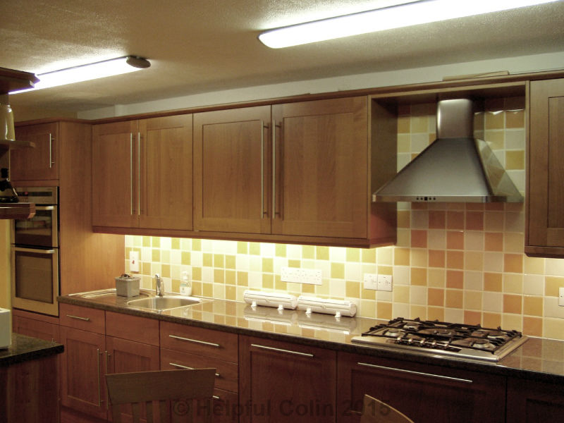
The wall cupboards above match the widths of the units below leaving a 760mm tiled gap above the hob with a suitable cooker hood mounted on the wall in that space. It would be 800mm except that when the cupboards are correctly installed they have veneered panels attached to their exposed ends, to match the wood of the doors, which are each 20mm thick. They are visible in the picture above entitled ‘Part of My Kitchen’.
Modifying The Pan Drawer Unit For Kitchen Appliance Connection Points

Here you can see my Pan Drawers. The top one is open so that the kitchen appliance connection points on the back wall can be seen. I removed the white hardboard back panel from the Pan Drawer Carcase when I built the kitchen.
Any wall mounted facilities may require the total removal of the back panel of a carcase or a hole to be cut in it to gain access. It’s best if all this work is planned and enacted during the design and construction of a kitchen.
Removing a unit’s back panel removes some of its strength. On its own it may want to turn into a parallelogram but if it is supported by units on either side which are complete with back panel or screws directly to a wall I doubt there will be a problem.
NOTE: Taking the back panel off a unit or cutting holes in it exposes its contents to any creepy crawlies hiding underneath or behind the units.
Although pan drawers are big, bulky and heavy when filled two people can lift them off their runners2 and remove them from the cabinet without removing their contents when the wall behind them has to be accessed. In fact the controls can sometimes be accessed through the drawer space (by people with long arms) when the drawer is just pulled open due to them having low backs. With a pan drawer empty and fully open it’s quite easy to reach through the drawer from the sides to the back wall.
Layout Of My New Kitchen Appliance Connection Points
When working out how to lay out the kitchen appliance connection points on the wall, proximity of appliances and length of power cords and hoses must be considered. I arranged for my appliances to be as near to the pan drawers as possible so that their power cords and hoses would reach. So my dishwasher is on the left, my washing machine is on the right and my fridge-freezer is to the right of my washing machine. You can see how my connection points for kitchen appliances are laid out below. Use it as a reference when reading the rest of this article.
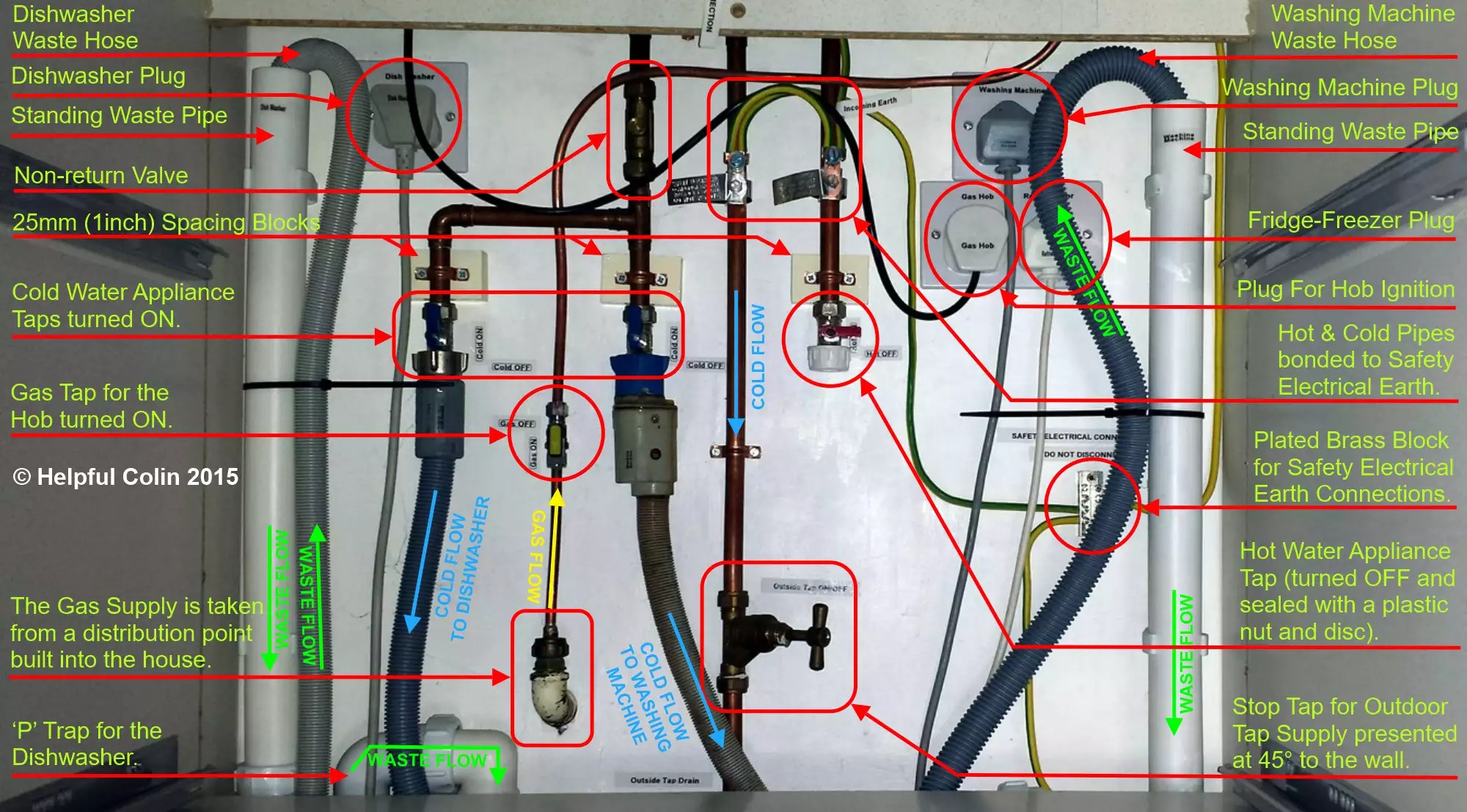
The List of My New Kitchen Appliance Connection Points, etc.
- Dishwasher Cold Water Feed,
- Dishwasher Cold Water Feed Stop Tap,
- Dishwasher Waste Water Drain Pipe,
- Washing Machine Cold Water Feed,
- Washing Machine Cold Water Feed Stop Tap,
- Washing Machine Hot Water Feed,
- Washing Machine Hot Water Feed Stop Tap,
- Washing Machine Waste Water Drain Pipe,
- Outdoor Cold Water Tap Feed Stop Valve,
- Outdoor Cold Water Tap Feed Drain Cock,
- Gas Hob Gas Supply Connection Point,
- Gas Hob Gas Supply Stop Tap,
- 13A Power Socket for Dishwasher (fed from fused spur with switch above the counter),
- 13A Power Socket for Washing Machine (fed from fused spur with switch above the counter),
- 13A Power Socket for Gas Hob Ignition (part of kitchen ring main),
- 13A Power Socket for Fridge-Freezer (part of kitchen ring main),
- Safety Electrical Earth Distribution Block (4-way Earth Terminal Block).
Wall Preparation For Kitchen Appliance Connection Points
The wall area behind my pan drawers was well plastered. Nothing had been attached to this area in the previous kitchen layout. I painted it with white emulsion to reflect light and keep it bright. The paint also ensured it would be clean so that I could stick DYMO labels next to the facilities.
Labelling My Kitchen Appliance Connection Points
Where possible the ON/OFF position for taps is marked by appropriate labels set horizontally or vertically next to each tap.
Power plugs and sockets are labelled to help identify which socket each plug must be inserted into so that each appliance is connected through the correct switched fused spur point above the worktop.
Mounting The Pipes and Taps
I determined water pipes must be 2.5cm from the wall to allow for taps to be attached and for appliances to be attached to the taps. I used simple but good quality chromium plated ON/OFF taps which have ‘nut, cone and olive’ pipe connections at one end and a ¾” BSP (British Standard Pipe) screw connection for appliance hoses at the other. The taps do not have any fixing holes for screws themselves so they require the associated pipework to be firmly fixed in place. The pipes near to the water taps are clamped with copper saddle clamps to 2.5cm thick painted wood blocks which have been screwed to the wall.
Hot and Cold Water Feeds
Because it’s not practical to have copper pipes crossing over each other just to get to a desired location careful consideration had to be given to the layout of these water facilities:
- cold supply to the dishwasher,
- cold supply to the washing machine,
- cold supply to an outdoor tap,
- hot supply to a washing machine (not usually required nowadays).
The feed pipes come along the wall, just below the worktop, from the sink area on the left with the hot pipe above the cold pipe. So the cold pipe had to turn down first with three branches for 1, 2 and 3 above on the left and centre in the picture; then the hot pipe could turn down for the hot supply in 4 above. The water feeds in 1, 2 and 4 above all have similar threaded stop taps to which the connection hoses from the appliances can be connected.
It turned out that hot water was not required for the AEG L10500VI washing machine I have, and probably never will be for any future washing machine. Washing machines are now nearly all cold fill, as far as I am aware. The reason is they are usually ECO machines which require very little water. This means that by the time the machine has sufficient water the hot water hasn’t yet arrived from the boiler.
Protecting Outdoor Pipework in Cold Weather
Outdoor taps have to be protected from frost in cold weather to prevent still water freezing and bursting outdoor pipes. Although insulation can be used on the outside, one certain way to give protection is to provide a Stop Valve and Draincock3 so that the following actions can be taken during freezing weather conditions.
- The water supply to the outdoor tap can be turned off with the stop valve.
- The section of pipe between the stop valve and the outdoor tap can be drained (into a suitable container) by opening the drain cock after the stop tap is turned off.
Then there won’t be any water left in the outdoor pipes to freeze.
Feeding An Outdoor Tap
I was able to fit the stop tap for the outdoor tap right in the middle of the available space by bringing the cold water feed down from a high level to a low level at that point.

At the point where the outdoor tap feed changes from a vertical pipe to a horizontal pipe, underneath the cupboard behind the plinth, I have inserted a drain cock at a point where there would otherwise be an elbow. Instead of fitting an elbow I have inserted an inverted ‘T’ (Tee) piece. Two points of the Tee connect to the vertical and horizontal pipes to work as an elbow while the third has a drain cock soldered into it. It is the type used to drain central heating otherwise known as a Draw Off Cock. I’ve mounted it at the lowest point in the feed pipe, but it has proved hard to reach and operate with a spanner because it is at the back wall and aligns with the bottom of the pan drawer carcase.
I should have extended the pipework to bring the drain cock to the front of the carcase just behind the plinth. This would give easy access to the drain cock once the plinth is removed.
Waste Water Drain Pipes
The waste water drain pipe for the dishwasher is on the left mounted vertically on the wall with the open top as high as possible. Similarly the waste water drain pipe for the washing machine is on the right. The appliance drain hoses hook into them in the standard manor and are ‘zip tied’ (fixed with a cable tie) to them to keep them neat and tidy. The flexible appliance waste hoses are tough and don’t stay where they’re put if they are left loose.
The height of the appliance drain pipes is an important factor with regard to the waste water outflow rate. If the dish washer, washing machine and sink all discharge waste water at the same time and it cannot get away fast enough, the water level in the standing drain pipes will rise and could overflow behind the pan drawers. Indeed if they are too low water discharged from the sink could back up and pour out of them at the back of the units. Their minimum height is usually specified by the appliance manufacturer. I would recommend having them as high as possible under the worktop with just enough space to hook the flexible hose in.
Waste Water Sewer Gas Traps
Both pipes connect to a horizontal pipe via individual ‘P’ traps (to hold back sewer gasses). The ‘P’ trap on the left is more like an ‘S’ trap because it feeds straight into a right-angled elbow taking the waste down into a Tee in the horizontal pipe. This horizontal plastic pipe also collects water from the sink (which also has a ‘P’ trap) before it couples to a narrower copper pipe through which it exits through the kitchen floor.
“I recommend the use of ‘P’ or ‘U’ traps wherever possible (as opposed to bottle traps). Bottle traps have a great tendency to get blocked up, but ‘P’ or ‘U’ traps are just made in the form of curved pipes so everything flows straight through them like any other piece of pipe.” — HC
Anti Gurgle Valve
I also have an Anti Gurgle Valve (also known as an Air Admittance Valve or Anti-syphon Valve) attached to the sink waste. This device allows air to be drawn in at that point and prevent gurgling noises from the sink waste when the washing machine or dishwasher discharge. Without such a valve the water in the sink trap gets sucked down the waste pipe, when the appliances discharge, until air gets sucked past the trap water. The trap water then oscillates back and forth in and out of the trap momentarily shutting off the air flow on each cycle. The gulps of air passing the trap water make a repetitive gurgling sound.
The Anti Gurgle Valve must be fitted after the output of the sink trap with the active element above the rest of the pipework. Get it wrong and waste water comes out of the anti gurgle valve and spills into the cupboard under the sink.
Power Sockets and Their Isolation Switches

Isolation Switches are on the wall above the worktop either side of the gas hob.
The socket appropriate to the dishwasher is placed below the worktop to the left of the pan drawer carcase and the sockets for the washing machine, fridge-freezer, and gas hob’s spark ignition unit are placed to the right.
There are isolation switches above the worktop for the:
- dishwasher,
- cooker hood,
- washing machine.
On the right is a picture showing these switches on the wall. They are actually switched fused spur units.

The one for the dishwasher is on the left and feeds the socket under the worktop for the dishwasher. Next to it is the Cooker Hood switched fused spur unit.
The output from the cooker hood fused spur unit is buried behind the tiles and feeds the connection point within the cooker hood. This powers the fan and two halogen lights built into it.

Similarly, on the right is the switched fused spur unit for the washing machine which feeds the washing machine socket under the worktop.
I have put Dymo labels (black with a transparent background) on the switch plates. I think it is important to Identify such switches so that users can turn off the correct appliance in an emergency. It is also important to locate these switches where they can be reached. They must not be behind a hob forcing a user to reach across a hot flame, heating element or pan to get at them.
The fuse ratings for the dish-washer and washing machine are 13A but the cooker hood fuse is only 3A. This is marked on the fuse holder on each spur unit so that when a fuse is changed it is known what the correct current rating should be. Relying on the rating of an existing fuse is not a good idea because another person may have inserted the wrong fuse previously.
Gas Connection
The gas connection (a permanent kitchen appliance connection point) for the hob is built into the house wall so the kitchen design took that into account when a place for the hob was chosen. When the hob was connected by the gas installer all the other pipes were in place so he screwed a 90° cast iron elbow with a BSPT (British Standard Pipe Tapered thread) into the iron pipe in the wall and reduced it down to the pipe size he chose to use. Then he threaded the thin copper gas pipe between the water pipes as best he could. So there it is with a small gas isolation tap in line with it.
Oven
The oven is not fed via the appliance connection points already discussed here but it does have an isolation switch of an appropriate power rating mounted above the worktop near to the oven cabinet.
Footnotes
1. Wet Chipboard
At a guess I would say chipboard swells by 5% when it gets wet and it then stays that size when it dries. It can burst out of a melamine coating. That’s how chipboard cupboards and shelves in kitchens (and bathrooms) get ruined. Ordinary wood swells much less and tends to return to its original size when it dries. If water gets onto anything made of chipboard it must be wiped up immediately.
2. Pan Drawer Runners
My pan drawers have an adjusting mechanism at both sides in the form of a rod going from front to back. It is rotated to adjust the drawer front into the vertical position. These rods must not be used as handles. Their fixings at the ends have no strength and cannot take the weight of the drawer. Permanent damage may result. Only lift the drawers up by placing hands under the tray. The handles at the front of the drawer should not be used to take the weight of a full drawer either.
3. Stop Valves and Draincocks
These can take many forms. There used to be brass units made all in one assembly just for that purpose. They were often used in outdoor toilets where the water had to be turned off and drained overnight in the winter to prevent burst pipes. The last time I saw a reference to one it was very expensive. Here is a modern equivalent.
I also installed Twin Towel Rails in my kitchen.
Leave a Reply