Introduction
Some people are very concerned that radio wave power coming from radio transmitters’ antennas will harm people. In particular people are troubled by mobile phone masts causing long term health problems when they are near to their homes.
I just want to make it clear how much a transmitter’s power diminishes as it spreads out from a transmitter. I’m sure some feel it must follow a simple linear law such as:
- double the distance and get half the power,
- triple the distance and get a third of the power,
- quadruple the distance and get a quarter of the power.
When in fact it follows an inverse square law which is nonlinear and gives this type of result:
- double the distance and get a quarter of the power,
- triple the distance and get a ninth of the power,
- quadruple the distance and get a sixteenth of the power.
This means the power (and damaging energy) is much lower than might be expected at any particular distance. Even within a short distance the power can drop considerably.
So, What Are Radio Waves?
Basic Description
This is just a quick explanation of what radio waves are so as to remind readers what is being discussed here. Radio Waves can also be referred to as electromagnetic waves or electromagnetic radiation for those who aren’t too sure.
All electromagnetic waves are made of electric and magnetic fields which propel energy carrying particles called photons at light speed. They can travel through space, air and some solid objects which are usually electrical insulators. They don’t tend to permeate conductors such as metal or salty water. See Encyclopaedia Britannica.
Electromagnetic Waves can be altered, absorbed, refracted and reflected by various materials they come into contact with on their journey.
The source of radio waves is usually alternating or varying direct electric currents flowing through some electrically conducting material. They can flow naturally or be man made, e.g. in radio transmitters. These currents create the electric and magnetic fields in the space and materials surrounding the conductors. Those fields naturally move away from the conductors as they are generated at light speed.
The frequency at which currents alternate can be fixed or vary. Those called Radio Waves have frequencies below 100 GHz. Above that frequency they are the same phenomena but are called by other names: e.g. light, X-rays, etc. See Fig. 2.
As the frequency climbs the method of manmade generation changes. With radio waves, frequencies are generated at low frequencies in electronic components and conveyed to an antenna, by connecting wires, to radiate. At microwave frequencies a Klystron could be used to drive the signal into a Waveguide. At infrared and light frequencies electricity is just used to heat a wire or filament in a bulb (or LED Lamp) which naturally generate the appropriate frequencies.
Properties of Electromagnetic Waves
Electromagnetic Waves have at least the following four properties (as well as polarisation properties):
- Energy E measured in joules or electronvolts,
- Propagation Speed c the “constant” speed of light which is ≈ 299×106 metres per second (where ≈ means “approximately equal to”),
- Frequency f (of oscillation) measured in Hertz (Hz), i.e. cycles per second,
- Wavelength λ measured in metres between the same two points of adjacent waves in metres or (at extra short wavelengths) Angstroms (Å) where:
1Å = 10-10m.
Term definitions:
- Å = Ångstroms (or Angstroms),
- λ = the small Greek letter Lambda,
- m= distance in metres.

NOTE: Any individual frequency is sinusoidal. Other recurring wave shapes are made from the sum of the amplitudes of that fundamental frequency and its harmonics, each with its own amplitude and phase relationship.
Properties of The Medium Through Which Electromagnetic Waves Travel
I’ve said that electromagnetic waves travel through space. Well space appears to have properties. It’s easy to think that these properties are embedded in space regardless of the presence of electromagnetic waves. But they may only be there as a consequence of electromagnetic waves being present. Who knows? Electromagnetic waves may only be the orderly fashion in which travelling photons present themselves. Check out Einstein’s view.
The properties I am referring to are Permeability and Permittivity. These permit the formation of magnetic and electric fields respectively. This is a requirement for electromagnetic waves since they are made of both these fields. Their energy is perpetually oscillating between them as they travel along. The properties that space has are seen as absolute because they cannot be reduced to lower values than these here:
- Absolute Permeability of Free Space µ0 ≈ 4π × 10-7 H/m (henries per metre). This was redefined on 20th May 2019 and is now determined experimentally. Previously it was exactly that value.
- Absolute Permittivity of Free Space ε0 = 1/(µ0c2) where c = the speed of light. This too was redefined on 20th May 2019.
NOTE:
- ε is the small Greek letter Epsilon,
- µ is the small Greek letter Mu,
- π is the small Greek letter Pi.
Other mediums made of matter have their own permeabilities and permittivities measured relative to the absolute values. The speed of light is lower through matter and matter is less permeable and permissible than space.
As an aside the speed of light c = 1/√ε0 µ0 in space and 1/√εr µr in matter.
NOTE:
- µr is Relative Permeability,
- εr is Relative Permittivity.
Charting The Electromagnetic Spectrum
All electromagnetic wave phenomena can be grouped together according to the frequency at which they operate. Radio Waves are just part of this broader spectrum which includes light, X-rays, Gamma rays and Cosmic rays. This spectrum is known as the Electromagnetic Spectrum and can be represented in diagrammatic form on a chart.
A search of the Internet will turn up a variety of graphical charts based on national and international agreements. They lay out all the radio bands plus the visible and invisible light bands that share the electromagnetic spectrum. Some of these charts are extremely complicated as can be seen in these examples:
- Here is the UK Frequency Allocation Chart for 2020,
- Here is the USA Frequency Allocation Chart for 2016.
So, I have made a chart to suit my needs, see Fig. 2 below. I studied a few charts on the internet and put this together using their best points.

Frequency & Wavelength Scales
At the top it has a green band with a logarithmic frequency scale covering the whole of the spectrum we know. This ranges from 1Hz (Hertz) to 1YHz (Yotta Hertz)

This is complemented further down on the chart by a yellow band with a scale displaying the wavelengths corresponding to the frequencies on the green scale. These range from 300Mm (Mega metres) to 300am (atto metres).

Note: wavelength = (speed of light) ÷ frequency
Where: Speed of light = 299,792,458 m/s ≈ 300,000,000 m/s
Frequency Bands & Their Organisation
Between the frequency and wavelength scales an orange strip has the names of the individual bands of frequencies we refer to when describing the phenomena.

Those with little energy per photon are on the left where we have Extra Low Frequencies (ELF). The energy level rises towards the right where we have Cosmic Rays. Yes, as this statement implies the energy level of individual photons rises with their frequency and is in fact proportional to it.
The Radio Frequency Bands, used for radio communication purposes, are very well defined by the International Telecommunications Union (ITU). I have shown their divisions, with abbreviated titles, in the left half of the orange band. There are eleven shown ranging from ELF to EHF. The highest Radio Frequencies are Microwaves.
Their names can be deciphered using the Abbreviations table in the bottom right of the chart which I have repeated here:

As an example VHF = Very High Frequency.
The Radio & Optical Division of The Spectrum
Between the green and orange bands another thin strip gives an indication which bands are in the Radio Spectrum (blue background) and which are in the Optical Spectrum (pink background).

The Microwave Part of The Spectrum
In radio communication all the SHF and EHF band frequencies are considered to be used for Microwave Communication and are allocated by the ITU.
Higher up there is an indeterminate Microwave area between 300GHz and 3THz. These microwave frequencies might be considered, by some, to be Infrared light (optical). So I have coloured them with blue and pink diagonal stripes to show they are part of the Radio or Optical Spectrums.

Sub Extra Low Frequencies
We can all argue about the lower end frequencies of the radio spectrum, since they really head down to zero, but require ever increasing power to radiate them well. Also there isn’t a useful bandwidth at these low frequencies, e.g. a voice bandwidth could easily take up all of the ELF, SLF, ULF & VLF bands.
If anything, extremely low frequencies have to be used with a narrow bandwidth for very low speed data signals or (obsolescent) morse. These low frequencies can just about penetrate sea water (as higher frequencies can’t) and may be used by submarines.
Ionising & Non Ionising Frequencies
Eventually as frequency rises the energy content rises to a level where it can ionise atoms (strip off their electrons). This can be damaging to atoms in the molecules of our bodies. So we have to be careful not to get irradiated by ionising frequencies. Those frequencies which are ionising (pink) and those which are not (blue) are indicated by this thin strip between the orange and yellow bands.

The Visible Light Band Expanded
In the centre below the main yellow wavelength scale, there is an expanded version of the narrow visible light band. It has the visible colours displayed and labelled in a central “rainbow” band.

This has its own green frequency scale above it and a yellow wavelength scale below it.
Please note: This visible light band has been drawn using a linear Wavelength scale. Its not logarithmic like the main wavelength scale. Consequently its Frequency scale isn’t based on the same logarithmic scale either.
SI Unit Prefixes
At the bottom left is a table describing all the SI Unit Prefixes used on the scales together with the powers of ten that they represent. You can see it repeated here:

As an example 1EHZ = 1 exaHertz which is 1 × 10¹⁸ Hertz.
Where Do Radio Waves and Other Electromagnetic Waves Come From?
Natural Radio Waves
In the natural world lightning is a common source, and in space stellar objects such as hydrogen stars like the sun, white dwarfs, neutron stars, magnetars, and black holes generate them. Even some planets emit radio waves. Take Jupiter for example.
Manmade Radio Waves
Manmade waves in the radio spectrum can be radiated from metal antennas (aerials) fed by high frequency alternating currents generated in radio transmitters.
Antennas are electrical conductors, usually dipole in style, which have photons created in the surrounding space by electrons being driven about in them. At low frequencies they are fed by specially designed feeder cables. At microwave frequencies radio waves start to behave differently and are fed by specially designed pipes called waveguides.
Heat And Light
Radiated heat comes from hot objects. Light traditionally comes from extremely hot objects. Modern methods for generating light try to be more efficient so that most of the energy deployed makes light frequencies and not unwanted heat frequencies. Remember the old tungsten filament light bulbs got very hot but LED lights are so much cooler.
Radio Wave Power
Powerful Sources of Radio Waves
Powerful Radio Waves can be broadcast by Radio and TV Transmitters sending out signals for public reception using hundreds of kilowatts. The military can use powerful transmitters too. Very powerful transmitters have to be used to send LF and MF signals over very long distances around our planet. This overcomes low frequency photons inability to carry large amounts of energy individually by increasing the number of photons sent.
Powerful Radio Waves are also given out by RADAR Scanners at places like airports and on ships. They can be seen mounted high up and rotating or in distant unpopulated parts of airports, out of reach of people, not only to suit their purpose but so that the more powerful ones don’t cause harm.
Microwave Ovens generate Powerful electromagnetic waves that are contained within ovens. They don’t come through the glass of the door because it has a screening grid on it which keeps them in. It’s a thin metallic sheet with many small holes in it stuck to the inside of the glass. The rest of the oven is made of impenetrable metal and gaps around the door are kept small. If all gaps are kept within certain dimensions these small wavelength waves cannot get through.
X-Ray machines at airports and hospitals generate electromagnetic waves too, but they are again contained or operated in controlled environments so as not to harm anyone.
Much of the equipment that would have generated dangerous radiation in the past gets replaced by modern equipment which doesn’t give out so much power. This is because sensors used to receive electromagnetic waves, that they give out, can be made much more sensitive today than in the past. So the transmitters don’t always have to give out so much power as previously.
Low Radio Wave Power Level Transmissions
Mobile phones using the latest networks often have cell transmitters which work over shorter distances than in the past, so less power needs to be sent from their masts. However there are more masts required to cover any particular area. Refer to this BBC report.
Mobile phones, cordless phones, Blue Tooth and Wi-Fi devices (i.e. routers, computers, printers, wireless headphones, computer mice, etc.) give them out too, but they are at low levels by design so that they aren’t likely to harm people. These devices have to meet international standards before they can be marketed. In most countries Wi-Fi Access Points transmit a maximum signal of 100mW at 2.4GHz and 200mW at 5GHz. See Ofcom’s message about power on these frequencies in the UK. The devices they connect with usually use lower power levels to return their signals.
Natural Sources of Radio Waves
Maybe some think that if all radio transmitters and similar devices were switched off that would be the end of the matter. However I have to point out that a lot of electromagnetic radiation is given out continuously by the sun. Even the light we see and heat we feel is electromagnetic radiation.
We all know that Ultra Violet light from the sun is dangerous since we’re advised to protect ourselves from it. So we protect ourselves with sun screen and clothing.
The main differences between light and radio waves are the frequencies involved and the energy the photons can carry. The only times we are free from all forms of radiation from the sun are:
- at night when the sun is screened by the earth being in the way,
- during a solar eclipse when the earth is screened by the moon.
The stars too give out electromagnetic radiation just like the sun but they are so far away it is insignificant by comparison. Cosmic rays would be very dangerous to us if they were in abundance, but they aren’t down here on earths surface. However for space travellers there are issues.
Radio Waves From Broadcast Stations
Radio Station Masts, TV Station Masts and Mobile Phone Masts usually broadcast their signals equally in all directions to communicate with many receivers in random locations. As a consequence the strength of the transmitted energy drops off as it spreads out to distant horizons.
Where possible these masts are designed to radiate most of their energy horizontally. This enables them to have the best reach, and at the same time they don’t send excessive power at a downward angle towards the ground nearby, or straight up into the sky.
Why Distance Usually Reduces The Radio Wave Power Received
The transmitted power of a radio signal can fall to a relatively low level even at a short distance from a powerful transmitter. I suspect people might accept that the power falls in proportion to the distance travelled, but can’t see how it can be inversely proportional to the square of the distance.
It’s this inverse square law which makes all the difference to the outcome from any dangers related to the radiated energy. If you’re not sure about Direct Proportion, Inverse Proportion or Inverse Square Law, then visit my post “An Explanation of Direct And Inverse Proportion” explaining them.
Ordinary transmitters tend to radiate their signals in diverging beams. This causes the power per square metre to diminish as the distance from the transmitter increases. What square metre do I mean? Look straight towards the transmitting antenna and imagine a square 1m × 1m in front of you. That’s it. Of course it doesn’t have to be square. Any shape whose area is 1m2 will do so long as the power is spread evenly throughout that area. See the example in Fig. 3 below.

How Divergent Radio Signals Propagate
Any divergent radio signal can be depicted as propagating from the centre of a sphere. To get out beyond that sphere it has to pass through its surface. Whatever shape cross section the beam has it can be marked out as that shape on the surface of the sphere in a diagram. That area will have a particular height, width and circumference. If the sphere’s radius is doubled then the height, width and circumference of the beam will be doubled too. See Fig. 4 below.

Did you notice? I just said the height, width and circumference of any shape drawn on a sphere increases in proportion to the sphere’s radius. So there is something which is directly proportional to the distance from the transmitter, but it’s NOT the 2D cross sectional area of the beam, it’s the 1D components, i.e. height, width and circumference around the beam.
Where:
- 1D = one dimensional,
- 2D = two dimensional.
The cross sectional area of the beam increases according to the square of the distance from the transmitter.
Exceptions Where Distance Makes Little or No Difference To The Received Radio Wave Power
So far I have referred to the common type of radio transmitter where the signal diverges when it leaves the antenna and diminishes as described. But, just to keep you informed, there are types of transmitter where that is not the case.
Concentrating Radio Wave Power With A Parabolic Dish
Some types of transmitter use a parabolic dish reflector like those used for receiving satellite TV signals. They concentrate the radio wave power into a parallel beam which wouldn’t lose energy if it weren’t for the attenuating properties of the medium (air and buildings) on the way to the receiver.
A similar parabolic dish is usually used to receive signals from this type of transmitter so that the energy doesn’t just wander past and get lost. Instead a large amount gets concentrated onto the antenna at the focus of the dish.
Communicating With A LASER Beam
Another type of transmitter where the power would not get reduced by divergence very much is one sending a LASER Beam. LASERs are exceptional for their parallel beams of light. Typically a LASER Beam has all its light running parallel so it doesn’t diverge along the way, except when passing through diffusing air, or travelling over very long distances. So, the intention is for the LASER beam at the reception point to have the same cross sectional area (CSA) as it does when leaving the transmitter.
If the transmitted power is 1 Watt per square millimetre and the beam has a CSA of one square millimetre then 1 Watt will be sent per square millimetre cross sectional area of the beam. Over short distances the beam won’t diverge so all the power will be received over one square millimetre too. The full 1 Watt of power will therefore be received because no power went anywhere else.
The issue with sending laser beams over long distances is with aiming the beam at the target receiver. See Pointing Is Key in this article from LaserFocusWorld.
Note: Light is attenuated and caused to be divergent by air molecules in a light beam. So, there may be a reduction in received power in the real world’s air for that reason. That attenuation wouldn’t take place in a vacuum like space.
The Harm Done By Radio Wave Power
People worry that their bodies may be harmed by radio wave power passing through them, regardless of the power involved. They aren’t sure if any transmitter is safe.
Some transmitters, like those used to broadcast radio and TV, are so powerful that they have to be turned off while engineers climb the aerial masts to work on them. This is for their own safety. If they aren’t turned off engineers may get RF (Radio Frequency) burns.
Transmitters with much lower powers may damage a few individual cells (damage which can’t easily be seen) by either killing them or making them cancerous.
What Causes The Damage?
Indeed electromagnetic radiation can do these things but only when the energy received is sufficient. It’s the energy that does the damage not the power alone. That energy comes from Power acting over a period of time. The type of damage done also depends on the radio frequency of the energy received.
See these articles for more information:
- Mobile phone base stations: radio waves and health,
- Radiation Burn at Wikipedia,
- Human Exposure to Radio Frequency Fields: Guidelines for Cellular Antenna Sites,
- Staying Safe Around RF,
- Radio Frequency and Microwave Radiation.
The Math Involved
The Energy Received And Its Relative Danger
The energy received depends on the power per unit area of the body and the length of time over which the reception of energy persists. i.e.
e = P × t
Where e = energy, P = power and t = time.
Depending on the specific circumstances some areas of a person’s body may receive more energy than others.
The risk from low levels of radio wave power needs to be weighed against other risks in life before getting overly concerned about it. See here a chart showing the chance of dying when engaging in certain activities. It may be you are very troubled by the radio wave power while being unconcerned about activities in this list which you participate in.
How Radio Wave Power Spreads Out
The power to be concerned about is not that leaving the transmitter but the power irradiating a person, animal or object. The radio waves from most transmitters are divergent, so they and their energy spread out over an ever increasing area as the distance increases from the antenna. The radio waves can be thought of as passing through a series of concentric spherical shells on their journey from the antenna. This means the energy and power per square metre diminish with distance. See Fig. 5.
Just because a transmitter’s antenna can be seen on a pole across the road, or high on a mast a few fields away, doesn’t make it dangerous where you are standing.
Some transmitter powers can be established by searching the internet for that data, e.g.:
Calculating Areas On The Surface Of A Sphere
This is where we have to dip into the associated mathematics to understand why power drops by a quarter when an area of any shape on the surface of a sphere quadruples due to the radius doubling. It all revolves around calculating the surface area of all or part of a sphere.
The basic formula for the area of a sphere is:
Formula 1
a = 4πr2
Where a = area of the sphere, r = radius of the sphere and π (pi) = 3.1459 . . .
For a portion k of a sphere the formula is:
Formula 2
a = 4kπr2
Where k <= 1 (less than or equal to 1), e.g. If we were dealing with one tenth of a sphere, k = 0.1.
A Practical Example Showing The Reduction Of Radio Wave Power With Distance From A Transmitter

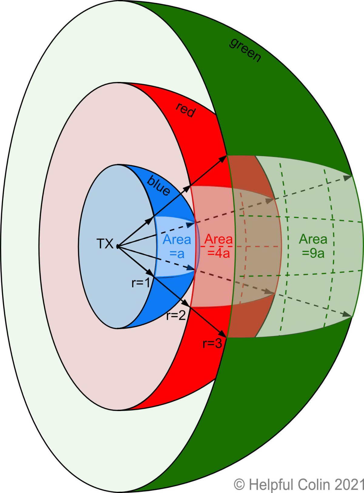
A radio transmitter TX radiates energy from an antenna (aerial) at the centre of a set of imaginary concentric spherical shells whose radii go up incrementally in 1m steps. The three innermost shells are shown in Fig. 5 and their properties are set out below:
- The inner Blue shell has a 1 metre radius,
- The middle Red shell has a 2 metre radius,
- The outer Green shell has a 3 metre radius.
Using A Pyramid Shaped Beam
For the purpose of this example I have chosen to use a radio beam constrained by its antenna to diverge in a beam with a square cross section. This makes it easier to demonstrate using diagrams.
With a square cross section, as depicted in Fig. 6, the beam is like a pyramid laying on its side with the transmitter TX at its apex and its base vertical. At the apex the four angles between the edges of the sides are all the same (θ Theta).

Description of The Squarish Areas Marked Out On Each Shell By The Beam
When the beam arrives at the surface of each shell it is contained within a certain area as per the following list:
- When the beam arrives at the Blue shell, with a radius of 1m (1 metre), the area of that shell within the beam is set to be 1m2 (1 square metre) by the design of the beam angles at the transmitter TX.
- Then, when the beam arrives at the Red shell, with a radius of 2m, the calculated area of it’s surface within the beam is 4m2.
- Similarly, when the beam arrives at the Green shell, with a radius of 3m, the calculated area of it’s surface within the beam is 9m2.
So, every time it passes through a shell it marks out the same squarish shape on it’s surface. But on any shell the area marked out by that squarish shape is larger than on the shell inside it, and that area happens to be the square of it’s radius.
(I’ve used the term “squarish” here because a square is a flat two dimensional object which is not compatible with the surface of a sphere. If you try to stick a square patch on a ball either you have to stretch it in places or let it have wrinkles to get rid of the excess material. The actual shape on the spherical surface when using a narrow pyramid style beam is slightly barrel shaped.)
The Purpose of Spherical Shells
The purpose of drawing spherical shells inside one another in Fig. 5 is to show how 4m2 on the Red shell actually looks like it is four times the area depicted on the Blue shell. It also shows how 9m2 on the Green shell actually looks nine times the area depicted on the Blue shell.
The math persuades us of the exactness of the areas. Our eyes can see that the shapes the areas are divided into in Fig. 5 are not square and not all the same, but may well have the same area.
NOTE: I am not the only one to use this method to demonstrate the inverse square law diagrammatically. Take a look at the Wikipedia version.
The Power Available At Each Shell’s Surface
At this stage no transmitted power is being absorbed by any load. It’s all free to continue radiating. So, the same power is passing through the squarish shape on each shell and all the power is available within that shape on any shell. That means at each shell’s surface the power per square metre must be less than on the squarish shape on the shell beneath since the power is constant while the squarish shape area increases with shell size.
Radio Wave Power per square metre = P ÷ A
Where:
- P = the power passing through the shell,
- A = the area through which it passes.
Read on to find out, using mathematics, the laws by which the area increases and the power diminishes.
The shell areas in Fig. 5 are labelled as follows:
- Ab = total area of the Blue shell,
- Ar = total area of the Red shell,
- Ag = total area of the Green shell.
And the portion of those shell’s areas through which the radio waves are concentrated is:
- Ab1 = the used portion of the Blue shell’s area,
- Ar1 = the used portion of the Red shell’s area,
- Ag1 = the used portion of the Green shell’s area.
The Radio Wave Power Per Square Metre Passing Through The Blue Shell
This shell has a radius r of 1 metre. So, the surface area Ab of the whole shell, in square metres (m2), is derived from Formula 1:
Ab = 4 × π × r2
Putting in values gives:
Ab = 4 × 3.1459 × 1 × 1
Ab = 12.566 square metres
As already suggested the beam’s square cross sectional pattern only passes through a portion of the shell. Not all of it. This is not unusual when antennas attempt to beam all their energy in one direction.
My example has all the energy passing out through 1 square metre of the surface of the first Blue shell which has a 1 metre radius, i.e.:
Ab1 = 1.0 square metre
That proportion k of the shell’s surface through which the radio signal passes is derived from Formula 2:
k = Ab1 ÷ Ab
k = 1 ÷ 12.566 = 0.0796
While the diverging angles of the beam are fixed the proportion k holds for all spheres regardless of their radius.
This brings me to a point previously mentioned under the heading, “How Divergent Radio Signals Propagate”. It’s not the area of a shape on the surface of a sphere which is proportional to its radius, but the perimeter of that shape. The area is proportional to the square of the radius.
The Radio Wave Power Per Square Metre Passing Through The Red Shell
By the time the radio waves have travelled another metre (double the original distance) they will be passing through the Red shell whose surface area Ar in square metres is:
Ar = 4 × π × r2
Ar = 4 × 3.1459 × 2 × 2
Ar = 50.265 square metres
Note: this Red shell has four times the area of the first Blue shell even though its radius has only doubled, i.e.:
Ar ÷ Ab = number of times Ar is bigger than Ab
Putting in values gives:
50.265 ÷ 12.566 = 4 times bigger
As with the Blue shell all the radiation will pass through the same portion k of the Red shell surface.
Ar1 = 50.265 × k
Ar1 = 50.265 × 0.0796
Ar1 = 4.0 square metres
Four square metres of the second Red shell have to share the power leaving one square metre of the Blue shell. While the Red shell has only double the radius of the first Blue shell, the power through just one square metre of the Red shell is now only a quarter of what it was for that same area of the smaller Blue shell.
The Radio Wave Power Per Square Metre Passing Through The Green shell
As the transmitted signal continues to radiate it will pass through the three metre radius Green shell. That has a total surface area Ag of:
Ag = 4 × π × r2
Ag = 4 × 3.1459 × 3 × 3
Ag = 113.25 square metres
Note: this Green shell has nine times the area of the first Blue shell even though its radius has only trebled, i.e.:
Ag ÷ Ab = number of times Ag is bigger than Ab
Putting in values gives:
113.25 ÷ 12.566 = 9 times bigger
This is nine times the area of the first Blue shell. Again the same proportion k of surface area will have the signal pass through it thus:
Ag1 = 113.25 × k
Ag1 = 113.25 × 0.0796
Ag1 = 9.0 square metres
Nine square metres of the the third Green shell have to share the power leaving one square metre of the Blue shell. While the Green shell has only triple the radius of the first Blue shell, the power through just one square metre of the Green shell is now only a ninth of what it was for that same area of the smaller Blue shell.
How A Conical Beam Just Doesn’t Make The Point
If the beam had been another shape in this example, e.g. conical, it would still be possible to divide it into four equal sized parts on the Red shell and nine equal sized parts on the Green shell by making the shapes look like segments.

However their layout looks so different on each shell that it’s difficult to see all segments as having the same area. So I chose the squarish style to make my point.
Radiation Intensity In The Vicinity of A Transmitter
Field Strength Meters measure the intensity of radio waves at varying distances from transmitters.
Fig. 8 and Fig. 9 below show how the Radiation Intensity drops as radio waves move away from an antenna. They show how the intensity falls to a percentage of the datum level measured at a distance of one metre from the antenna.
Setting The Distance of The Datum Level
Some masts have a circular array of antenna, all radiating the same signal, placed around their mast and equidistant from it. If the datum level is set at zero distance from the centre of the mast it’s difficult to determine its value. So I have chosen to set the datum level as that measured at 1m. This may not be the best choice but levels at other distances can at least be calculated using whatever distance is chosen.


My Other Posts About Radio Devices
- Radio Controlled Wall Clock In My Shed
- Extending The Door Bell In My Home
- Terrestrial Freeview TV Aerial Direction
Leave a Reply