Post Description
I’ve been extending the door bell in my home so it can be heard in the house extension and shed. It’s been done by incorporating wireless technology, while retaining my original 1980s “DING-DONG” door chime which had a great sound and an illuminated bell push.
Introduction
I can’t hear the door bell, fitted in the hall, when I’m in my extension, shed, or outside. I first considered wiring a similar door bell (it’s actually a “Ding-Dong” door chime) in parallel and bought one for that purpose.
The door chime I bought was a Friedland D117 Ding Dong. It’s their modern version of the original and certainly looks the part, except the base plate is white instead of brown.
The plan was to mount the new one in the extension. Then run a connecting cable to the original in the hall. It would have run through the extension’s loft space and under a bedroom floor.
Time passed with no further action by me, and I thought about it some more:
- I needed a third door bell outside or in the shed.
- I didn’t want to run the interconnecting cable through those difficult places.
- I also suspect that the bell transformer won’t give out sufficient power to drive two similar door chimes.
So I abandoned the idea of them being connected in parallel.
I reckoned that if I could get the original door bell to drive a relay, which didn’t require much power, I could get it to short out the contacts of a battery powered wireless doorbell button.
I looked for a suitable wireless door bell and found one at Easylife. It was a UNI-COM Portable and Plug-in (Wireless) Door Chime Set (no longer available). I then made it operate from the original bell push along with the original door chime.


Electrical Safety While Extending The Door Bell
Door bells run off a low voltage supply, either using AC from a mains transformer or DC from batteries. The voltage isn’t likely to be more than about 20 volts. So the voltage used to operate the bell is safe.
If a transformer is used then the danger comes from the primary side (the mains side). Anyone connecting the mains side of a transformer must be competent to do so. Ideally it needs to be wired through an isolation switch.
Door bell’s consume a low level of energy so they can be connected to a lighting circuit fused at 5 amps (or a 6 amp RCD). A light switch can then be used as an isolation switch. Else they can be connected to a fused spur (with a 3 amp fuse) off a ring main or they can be cabled to a mains plug with a 3 amp fuse.
Working on the secondary side (the low voltage side) is safe as long as the transformer is in good condition.
NOTE: If there is a transformer fault there can be a breakdown of insulation between the primary and secondary winding. This can make the secondary side become live and dangerous.
Bell transformers should be well made because they are expected to be permanently connected to the mains for years, just as mine has been. So they shouldn’t get too hot and become a fire hazard.
What I Had Originally Before Extending The Door Bell
I began with what would now be considered an old door bell. It’s a Friedland Door Chime from the 1980’s that gives a “Ding-Dong” sound. There are two vertical chime bars which are struck by the core of a solenoid. One as it is driven through by electric current, and the other as it returns driven by energy stored in a spring. It overshoots its starting position to strike the second chime bar.
The original door chime has operated for 39 years powered by a bell transformer mounted above the hall ceiling. It’s connected to the lighting circuit via a switch. The sole purpose of that switch is to disconnect it should there be a fault. It isn’t a true isolation switch because it only disconnects the live wire and not the neutral.
In all that time the transformer hasn’t gone faulty. However the door chime has, from time to time, accumulated dust which impairs the thrust of the solenoid core. So it has to be dismantled and cleaned every few years. Otherwise it’s in good shape.
How A Ding-Dong Door Chime Works
The door chime has an electromagnetic solenoid (SL1). It contains a confined ferro-magnetic (NOT magnetised) projectile which strikes one chime bar when energised and the other (with energy stored in a return coil spring) when de-energised. So when the button is pressed and the electrical circuit is completed the first chime goes “Ding”, then when the button is released and the circuit is broken the second chime goes “Dong”.
Battery or Transformer
These door chimes can often be powered by batteries. In my case there would be 4 × 1.5V ‘C’ cells in series supplying a total of 6V.
Alternatively they can be powered by a bell transformer giving an AC supply between 8V and 16V. The solenoid and bell push are wired in series across the supply.
Using A Transformer For An Illuminated Bell Push
When the bell push has to be illuminated the transformer option is the only feasible one. Batteries continually connected to a light would soon run down.
The schematic diagram for this option is shown below in Pic. 1:
Pic. 1. Schematic of A Door Chime With Illuminated Bell Push Powered via A Mains Transformer

NOTE: This method was used for years before the modern era. It allowed a bell push (button) to be illuminated and operate a door chime using a 2-wire cable between the two.
Detailed Operation
The solenoid and the lamp (LP1) are wired in series, The light draws enough current from the transformer to illuminate, but not enough to energise the solenoid. When the bell push is pressed it shorts out the lamp and the full potential is applied to the solenoid to energise it. Releasing the bell push lets the lamp light again and reduces the solenoid current letting it de-energise.
When The Solenoid Is Energised
When the solenoid is energised the ferro-magnetic striker is pulled into the core of the solenoid against a light spring. It overshoots its final resting position and strikes a chime bar due to its momentum. It then bounces off the chime bar and comes to rest away from it, leaving it to ring. If it remained touching it would dampen the ring.
When The Solenoid Is De-energised
When the solenoid is de-energised the magnetic striker is pushed back through the core of the solenoid by the spring. It overshoots the starting position and strikes the other chime bar due to its momentum. It then bounces off the chime bar and comes to rest away from it, leaving it to ring.
Extending The Door Bell Using Wireless Technology
In simple terms extending the door bell involved wiring a relay in parallel with the existing door chime’s solenoid. Then I connected the relay contact in parallel with the wireless door bell’s bell push button. So, when the existing bell push is operated, the old door chime will “ding-dong”, as usual, and the wireless door bell will be triggered via the relay.
Why I Want To Continue Using The Old Bell Push
The reason is simple. The old bell push is permanently illuminated so it can be seen in the dark. See my post entitled: Converting A Bell Push Lamp To LEDs. This is the one let-down of wireless door bells, their bell pushes aren’t illuminated in the dark. That’s because they’re battery operated and the battery would soon run down if it had to power a lamp too. I’m sure this is usually overcome by:
- having an outside light permanently on,
- having a PIR (Passive Infra Red) sensor to illuminate a nearby light when someone goes near enough to operate the bell push.
I also prefer the sound of the existing electromechanical door chime so I need the old bell push to operate it.
The Wireless Door Bell Used When Extending The Door Bell
When I was extending the door bell I used a UNI-COM portable & plug-in wireless door chime set which has:
- 8 chimes (tunes),
- a volume of 85db(A),
- a wireless range of 120m.
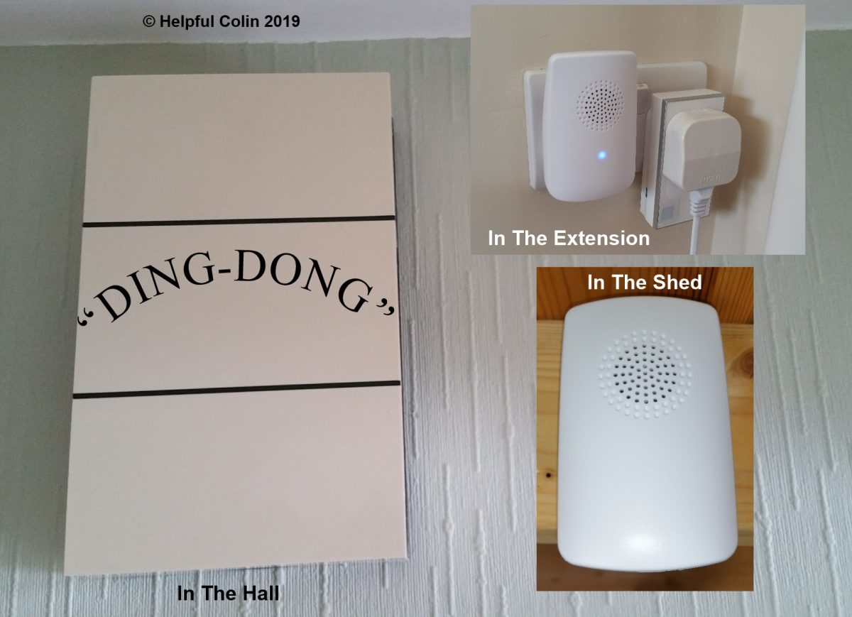
The set consists of three units:
- the bell push wireless transmitter powered by 1 × CR2032 button cell,
- a mains powered receiver & speaker unit,
- a (2 × AA) battery powered receiver & speaker unit.
These three units are shown below:
Pic. 2. UNI-COM Bell Push, Mains Unit & Battery Unit.

Pic. 3. Wireless Bell Push Housing

In this picture the bell push housing has had the transmitter circuit board removed. It was hooked in at the top and fixed with one screw at the bottom.
Unfortunately I removed the board and built it into the original door chime without first taking a picture of it in the housing.
The two parts of the housing have two lugs which simply click together.
Fitting The Wireless Bell Push In The Original Door Chime
First I enlarged the wireless bell push transmitter circuit board’s fixing hole to 3mm.
Then I attached the two white wires in the picture below. These are soldered to the wireless bell push button contacts. Once mounted on the Veroboard® these soldering points aren’t accessible.
Pic. 4. The Underside of The Wireless Transmitter

Next I mounted it on a piece of 0.1 inch matrix Veroboard® with a threaded standoff pillar and two M3 screws. The Veroboard® also holds the following components:
- the 12v relay A,

- the electrolytic capacitor C1 (470μF 25v),

- the bridge rectifier BR1 (1A 50v),

- strip board (Veroboard®).

These can be seen in:
I drilled 2 × 3mm holes in the Veroboard® to hold it to the door chime base into which I drilled similar holes. I then fixed them together with 2 × 3mm screws.
Once the boards were mounted in place the two white wires from the transmitter bell push could be terminated on two soldering points on the Veroboard® which go to the relay contact.
Finally I used some single insulated twin flex to connect the bridge rectifier AC input soldering points to the solenoid connections 0 & 3.
The finished work is shown below Inside The Modified Door Chime:
Inside The Modified Door Chime
Pic. 5. View Inside The Modified Door Chime

The Modified Door Chime Schematic
The schematic diagram for the whole arrangement is shown below:
Pic. 6. Modified Door Chime Schematic

Modified Door Chime Schematic Circuit Description
The mains supply is fed to the bell transformer (T1) via a switch (S1). The switch offers disconnection of the live feed ONLY in any type of emergency situation, or just to silence the door chime.
The secondary winding of the bell transformer (T1) provides an 8V to 16V AC supply depending on the load.
The solenoid (SL1) used to strike the chimes is in series with a modified bell push (S2). This now has LED illumination since I converted the light from an incandescent lamp. (See: Converting A Bell Push Lamp To LEDs.)
The alternating potential applied to the solenoid (SL1) is rectified by the bridge rectifier (BR1) to produce a DC supply for the relay. The 100Hz ripple, produced by the full-wave rectification, is smoothed by the 470μF 25V reservoir capacitor (C1).
When the relay (A) operates its contact (A1) shorts out the wireless bell push button’s contact. That triggers the wireless transmitter into sending a signal to the receiving units to make them sound their chime/tune.
The wireless transmitter is still powered separately by a CR2032 3V lithium button cell as originally supplied for the UNI-COM equipment. If it turns out that it requires regular replacement, I will consider building a 3V stabilised supply fed by the bell transformer.
Leave a Reply