Introduction
I have a Drayton 3-Port Valve Actuator MA1 controlling the mechanics of a Drayton 3-Port Valve used in my central heating system. Specifically, a “BIFLOW SYSTEM”, with one boiler (not a combination boiler) where the Hot Tap water is isolated from the Central Heating water and Mains supply and stored in a Header Tank (when cold) and Copper Cylinder when heated.
Over time valve actuators may develop faults which are easily fixed by replacing them. I have just had to do that with the one in mine. I last changed it on 12th December 2017, so, it had run for nearly five years without a fault.
Safety Notice
The work involved here does not interfere with the gas supply to the boiler.
Anyone working on the electrical controls for central heating should be suitably qualified and understand the dangers of working with 240V A.C. Mains electricity.
The electrical supply to the Central Heating MUST be isolated by a double pole switch or other adequate means before work commences.
Repairing actuators is possible but I recommend only skilled electricians do this so as not to leave an actuator in dangerous condition. I also consider it something to do away from site in clean conditions on a bench. Depending on the problem, spare parts may have to be obtained.
Obtaining A New Actuator
The Drayton 3-Port Valve and Actuator MA1 can be bought together as one unit but that is very expensive when there is no need to replace the valve. If the valve isn’t leaking any water at the spindle driven by the actuator, and the spindle turns freely through about 30° (don’t force it), it’s very likely the valve is OK. The valves usually last many more years than the actuators.
NOTE: Similar valves are made by other manufacturers, but as far as I am aware actuators are not interchangeable with other brands of valve. Both valves and actuators of a particular brand are different to other brands.
My 3-Port Valve Actuator Fault
The type of fault on my system was intermittent, causing hot water to be fed to both the radiators and the hot water cylinder at times when it should only have been fed to the hot water cylinder.
In this situation the indicator shows the valve set to the Mid Position when the Room Thermostat is NOT calling for heat. This is caused by the actuator getting stuck in this position when it should have returned to Hot Water only.
So, what goes wrong with Actuators?
How A 3-Port Valve and Actuator Work
The 3-port valve is shaped like a capital letter T with the hot water from the boiler connected to the Input Port (vertical part of the T). Then the water branches to Port A (top of T right) or Port B (top of T left) or in both directions at once, as directed by the actuator vane position. See the labelled picture below.

Electrical Connections
The 3-port Actuator has a 1m cable with five wires to convey power to it and communicate control signals and provide a safety earth (see below). This is a picture showing the usage of the colours.

These are the colours of the wires and their usages:
- Green/Yellow (the Earth connection),
- Blue (the mains Neutral connection),
- Orange – Cylinder Thermostat ‘Calling for Heat’ connection,
- Grey – Cylinder Thermostat ‘Satisfied by Heat’ connection,
- White – Room Thermostat ‘Calling for Heat’ connection.
The wires are connected to the central heating control circuitry via terminals in a nearby LWC1 Wiring Centre (connection box).
The Water Directing Vane Within The Valve
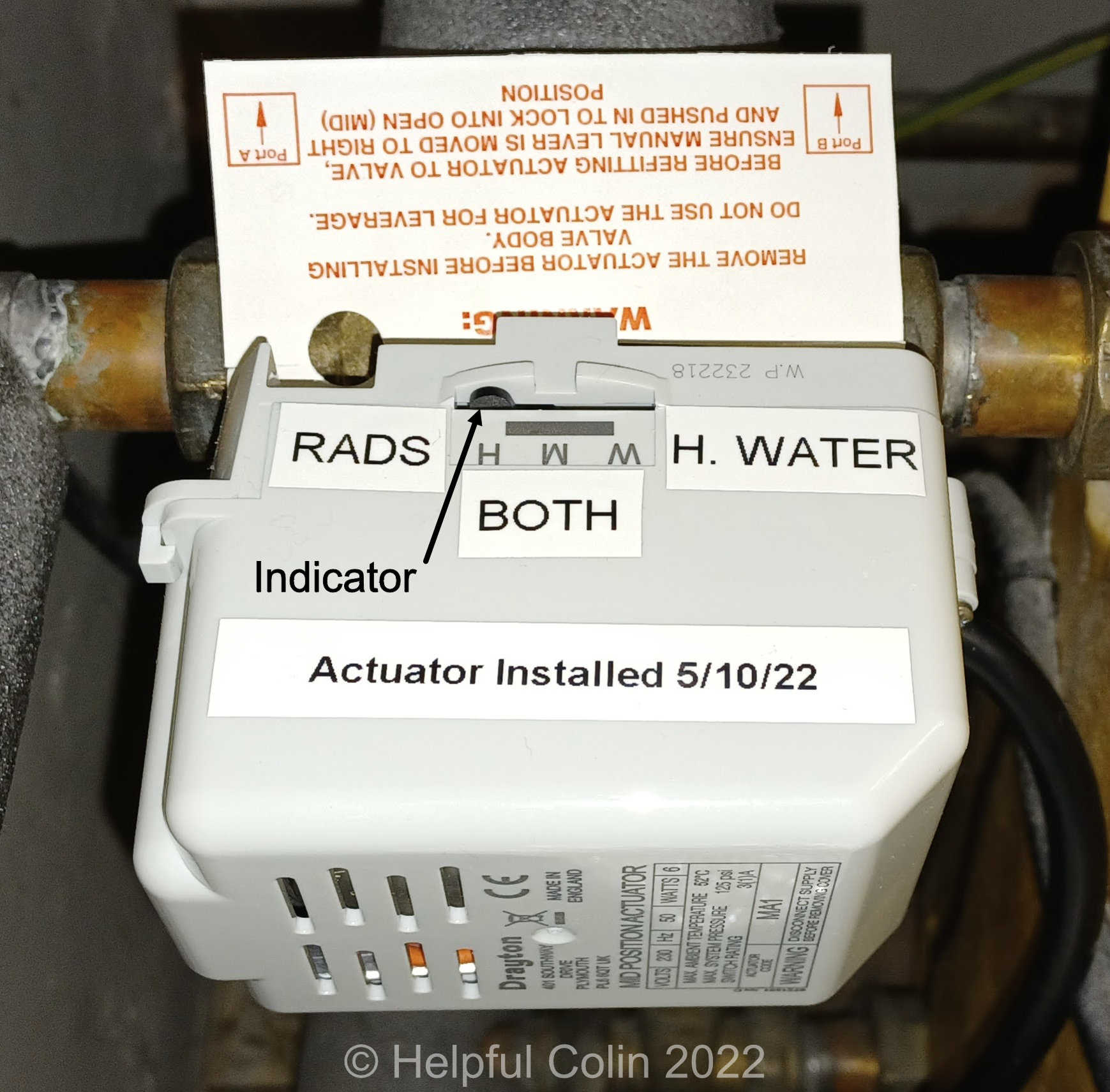
Inside the valve is a movable plastic vane and on the outside, there is a corresponding indicator. The vane has 30° of movement and directs the water to the following places as indicated by the letters W – M – H marked on the actuator cover:
- W (Hot Water) – The Hot Water Cylinder when only the hot water thermostat calls for heat,
- M (Middle position) – Both the Hot Water Cylinder and Central Heating Radiators when both thermostats call for heat at the same time,
- H (Heating) – Just the Central Heating Radiators when only the room thermostat calls for heat.
In my case the valve is in an attitude such that all ports are fed by horizontal pipes. This causes the letters on the actuator cover to be on top, as I view it, but upside down to read. So, I have put labels on the cover to clarify their meaning as you can see here:

NOTE: These labels make it very easy to check what is happening with water flow when the system is acting suspiciously.

Changing A 3-Port Valve Actuator
Replacement Processes
- Turn off electrical supply to the Central Heating System to make it safe,
- Uncover the terminals in the LWC1 Wiring Centre (Connection Box) that the actuator wires connect to,
- Make a note of the terminal positions of the five coloured wires (take a photo),
- Disconnect the wires from the terminals,
- Unthread the cable from the terminal box, capping, etc.,
- Disengage the Actuator from the Valve by pressing the button and withdrawing it from the vane spindle,
- Engage the new Actuator with the Valve and press it into position until it clicks,
- Thread the cable into the terminal box to reach the terminals,
- Connect the five wires and ensure they won’t pull out of the terminals,
- Replace the LWC1 Wiring Centre (Connection Box) cover,
- Switch on the Central Heating System and test it.
Images Associated With Each Process
These are colour coordinated with the above list of Replacement Processes.
Process 1. Turn OFF The Electrical Supply to The Central Heating System. This is a Safety issue.

Processes 2-5 & 8-9. Typical 3-Port Valve Actuator Wire Connections to A Central Heating System.
In my heating system all the wires from the actuator terminate in a LWC1 Wiring Centre (connection box) nearby. The two pictures below show the connection box with the lid removed. Inside the lid is a label explaining what each connection terminal has connected to it.
A “TWINZONE SYSTEM” has two × 2-port valves. One to supply the radiators and the other to supply the hot water cylinder. Here the descriptions above the terminal numbers apply.
A “BIFLOW SYSTEM”, like mine, has a 3-port Mid Position valve. Here the descriptions below the terminal numbers apply.
All Earth connections go to one group of six terminals while Neutral connections go to another group of six. Short wire straps link each terminal to the others in its group.
Abbreviations used on the label:
- BLR = Boiler.
- CALL = Call for heat.
- COM. = Common connection.
- CYL = Cylinder.
- HTG = Heating.
- H.W. = Hot Water.
- L = Live
- N = Neutral
- SAT = Satisfied.
- STAT = Thermostat.

To change over the wires, loosen the terminal screws for the old actuator wires and pull them out. Then thread the new actuator wires in place and put them in the same terminals as the old ones (colour for colour) and tighten the screws.
Afterwards give each wire a little tug to make sure it won’t pull out.
NOTE: In my system the grey wire has another red wire connected to the same terminal.
Processes 6-7. How The Actuator Physically Engages with The Valve.
A quick release catch holds the actuator onto the valve by engaging a flange near the vane’s spindle. A button, cunningly threaded through the plastic case, as indicated by the dashed lines drawn on the image below, operates this catch. A plastic hairpin spring, shown, returns the button to its normal position. This makes the job of mechanically changing the actuator very easy.

Below is the actuator seat on the valve. There are just two peg supports and the flange which the catch latches behind. The vane spindle flats have to engage with the rotating output shaft on the actuator. So, to align them for reassembly:
- Turn the vane spindle to mid position using pliers, or an adjustable spanner, and set the actuator to mid position using the manual lever as per instructions.
- Or, as I do, turn the vane spindle fully clockwise and put the actuator on the valve while power is off. In this condition the return spring inside the actuator will hold it in the correct position (for Hot Water).

Process 10. Replace The LWC1 Wiring Centre (Connection Box) Cover.

Process 11. Turn ON The Electrical Supply to The Central Heating System and Test It.

Testing Processes
During tests and normal usage, I find the position of my indicator is a little inaccurate, but it doesn’t seem to have a detrimental effect.
- To check that only the hot water cylinder is being heated:
- Temporarily turn down the room thermostat below normal so it doesn’t call for heat.
- Temporarily turn up the cylinder thermostat above normal so that it does call for heat,
- Check that the actuator indicator points to W, the boiler fires up and begins heating the hot water,
- To check that only the central heating radiators are being heated:
- Temporarily turn down the cylinder thermostat below normal so it doesn’t call for heat.
- Temporarily turn up the room thermostat above normal so that it does call for heat,
- Check that the actuator indicator points to H, the boiler fires up and begins heating the radiators,
- To check that both the hot water cylinder and the central heating radiators are being heated together:
- Temporarily turn up the room thermostat above normal so that it calls for heat.
- Temporarily turn up the cylinder thermostat above normal so that it calls for heat too,
- Check that the actuator indicator points to M, the boiler fires up and begins heating the hot water and the radiators,
- When all tests give correct results:
- Return all thermostats to their normal working settings.
I have another Central Heating post here:
How I Hung My Vertical Radiator in The New Lounge.
Leave a Reply