Introduction
This post covers some of the practicalities that have to be met when building a function generator (signal generator) using an XR2206CP Function Generator kit.
I assume anyone building one of these kits has some electronic and soldering experience.
The Kit Instructions
I bought two of these kits and I could see immediately, when I tried to read the instructions, that there was a problem. So I had to interpret them.
You can see my interpretation of the kit provider’s instructions in my post “XR2206 Function Generator Kit Improved Instructions“. You should read them before assembling the kit. The instructions contain the schematic diagrams.
Safety
Eye Protection
Eye Protection should be worn when soldering and snipping off wires that fly into your face.
Tools Required To Build This Function Generator Kit
- Magnifying Glass,
- Soldering Iron,
- Solder 0.7mm dia.,
- Printed Circuit Board (PCB) holder,
- Small nippers to trim soldered wires,
- A Philips screwdriver.
Magnifying Glass

A must have for working with small modern electronic components is a Magnifying Glass (see the example above) to enable viewing of the component values printed on them. Particularly small resistors and ceramic capacitors like the ones used here.
Soldering Iron


A temperature controlled soldering iron is good for working on printed circuit boards (PCBs). I set the temperature to 300°C. That’s high enough to melt the solder but not so high that it will cause the copper strips to come away from the board. With this particular model the temperature cycles between 295°C and 305°C.
PCB Holder

This is a new tool I’ve recently acquired for holding PCBs. The PCB is placed between the two jaws by resting it in the grooves and the spacing is adjusted so it is held under spring tension. The board can be rotated by 360° around a horizontal axis. It can be seen being used in other pictures in this post.
Small Wire Cutters (Nippers)

These nippers can fit in any narrow spaces and the jaws lie flat against the board to crop the wire ends of components very close to it.
Philips 2pt Screwdriver

A Philips 2pt screwdriver is required to tighten the screws supplied for holding the acrylic case together. The screws supplied with nuts also require a Philips 2pt screwdriver but those screws aren’t long enough to do the job.
Building This Function Generator Kit
Components Provided

The picture above shows all the components which have to be mounted on the circuit board when building a function generator using an XR2206CP chip.
1. Soldering The Resistors
Ultimately all the components have to be threaded through the holes in the circuit board from the top side (where the text is printed), And soldered on the other side.) When doing this manually it’s best done in stages commencing with the components that have a low profile, e.g Resistors and IC Sockets. Then if the board has to be laid upside down on a bench to work on the solder side it won’t wobble about too much in the early stages.

To prevent components falling out of the board when it’s turned upside down the wired components at least can have the wires splayed out. By that I mean they can be bent at 45° in opposite directions so that they can’t drop out when turned upside down.

At this point three hands are required to hold the soldering iron, solder and board.
I’ve solved this difficulty by using a PCB holder. This can be used to hold the board in a variety of positions so I can put components in from one side then turn it over to solder them. You can see it in use here.
Previously I have used a small rubber jawed vice that clamps on the edge of the bench shown below.

2. Soldering The Low Profile IC Socket
There is only one IC socket in this kit which I managed to hold in situ with an elastic band, while it was tilted upside down and soldered.


3. Soldering The Electrolytic Capacitors
I’m not sure why I didn’t install the ceramic capacitors first since they are smaller.
There are only three electrolytics in this kit. They are small but stick up and can prevent the top of the case from fitting on. So either they have to be left sticking up so that they can be bent over or remain vertical but pressed hard down to the board.

Electrolytic capacitors are polarized. The -ve wire is shorter than the +ve wire and has a white stripe on the body with -ve signs on it. The -ve wire has to be connected to the hole marked with Hatching on the top side of the board. The spacing between hatching lines on the circuit board is 1mm. I have marked this image with a + sign for the long +ve wire’s hole.

4. Soldering The Ceramic Capacitors
I’m not too sure why I didn’t fit these before the electrolytic capacitors after all they are smaller.
The ceramic capacitors in this kit are physically small and the coded values have to be read by many people using a magnifying glass. They too have to be threaded through their holes and have their wires splayed out to retain them when turned over and soldered.
5. Fitting The Larger Components
Some of the larger components like the Potentiometers and the Power Socket have bulky tags. Normally I would probably leave them unbent but with this board being a tight fit in its case they are a problem.
I found out with the first one I built that they were protruding too much and had to revisit them and melt the solder so I could bend them hot by pushing on them with the tip of the soldering iron. This is potentially dangerous and I advise people to get these tags bent flat against the board before soldering.
Even bending them before soldering can be dangerous. If you can only do it by pressing the tags with a tool that will push the tag into the bent position you must hold the board with a leather gloved hand. Any slip of that tool and it could plummet straight through the board (breaking it) and carry on its journey through the palm of the hand holding the board.
When the tags are bent over they can be soldered. The header pins don’t need bending. Try to solder two diagonally opposite tags. These can be reheated to push the whole strip nearer the board. Once it’s in position all the other pins an easily be soldered.
6. Installing The XR2206CP IC
Having completed all the construction soldering I conducted a visual inspection to ensure there were no solder blobs that would cause short circuits. I then installed the XR2206CP integrated circuit as per the instructions.
7. Testing The Function Generator
I used a 12V 2.5A D.C. mains power supply which had the correct diameter plug on its output cable to power this function generator.
I also had to connect short wires to the three output terminals on the function generator board so that I could then connect the probe of my oscilloscope to it to observe the output waveforms.
8. Fitting The Function Generator Into Its Acrylic Case

As long as the Front Panel and base are squeezed together, to prevent the side’s tabs disengaging, the case will stay wrapped around the circuit board and its components. The Front Panel and base are therefore held together by four M3×15mm screws. The screws pass through the Front Panel and tap their own threads into specially designed holes in the base.
The kit also provides four M3 × 5mm screws and nuts to clamp the circuit board onto the Base. In my opinion those screws are just not long enough so I have not used them. The circuit board is a little loose in the case but, for what it is, it’s not too sloppy. I may use my own screws later.
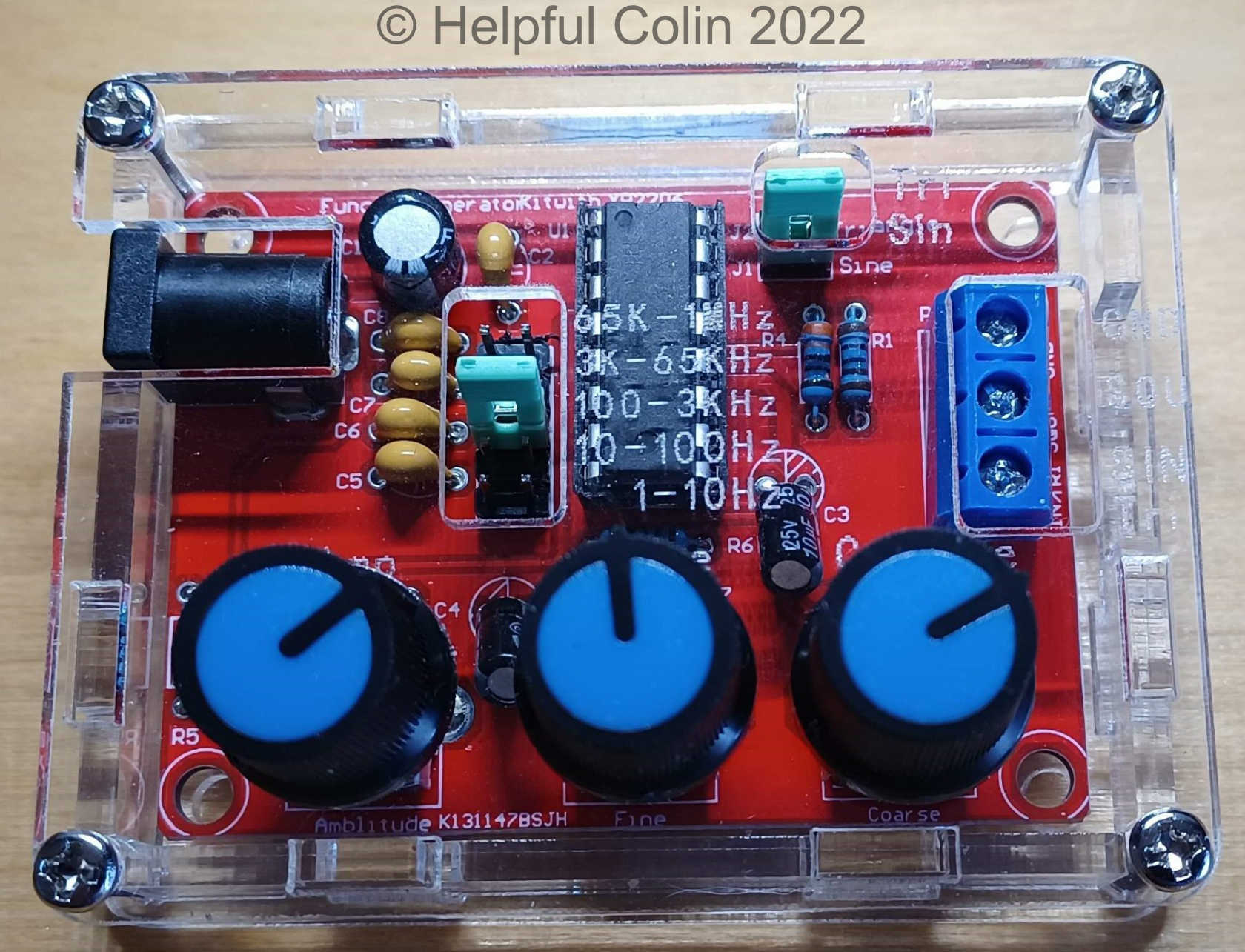
When mounted in the case the three control knobs can be pushed onto the splines of the potentiometers easily with their pointers positioned as desired.
Leave a Reply