Introduction
The XR2206 Function Generator Kit is available through various outlets at a selection of prices up to £13. I got one branded “ARCELI” via Amazon for £7.99.
Having got one, I would advise getting the cheapest one you can. Just take into consideration the trustworthiness of the seller to be sure you get what you’ve ordered, paid reasonable post and packing charges for, and that you will actually receive it.
Having looked at pictures of the finished article I suspect all brand’s circuits are the same but each brand may source their components differently.
Now you can see my other post “A Function Generator Built From A Kit Using An XR2206” to see how I got on with building these kits.
Quality of The Kit Parts
The Electronic Components And Circuit Board
I found the quality of all the parts to be good. All components were like all those used in modern electronic equipment. All the resistors had the same power handling capacity of a ¼W. This was reasonable for a low power device such as this XR2206 Function Generator Kit.
Similarly the electrolytic capacitor voltage ratings of 25v was ample.
The preparation of the circuit board was excellent too. Feed-through holes, tinning and lacquering, all looked good to me. Tinning solder had flowed well around the holes.
The Transparent Acrylic Case
All components are attached to the circuit board and the whole is expected to be housed in a Transparent Acrylic Case. This case has six faces all cut out from transparent acrylic sheet 2.5mm thick. The six faces consist of four sides a top (Front Panel) and a Base. The Front Panel is engraved with labels for the controls.
The case is held together around the circuit board by tabs on the edges of the four sides which fit into slots on the Front Panel and base. The case parts are nicely presented and look as if they were cut out and engraved with a LASER.
The Controls
There are three rotary control knobs (as viewed with the Power Jack on the left):
- The Output Level control is on the left. Weirdly it has to be turned ANT-CLOCKWISE to increase the level.
- The Course Frequency control is in the centre.
- The Fine Frequency control is on the right.
There are two sets of links for controlling Frequency Bands and Waveforms:
- The Frequency Band control is in the form of a five position link:
- 1Hz-10Hz,
- 10Hz-100Hz,
- 100Hz-3kHz,
- 3kHz – 65kHz,
- 65kHz-1MHz.
- There is another link control with two positions:
- sine wave,
- triangular wave. This affects the output waveform of the Sine Wave output connection.
The Connections
There are three screw terminals on the right (P1) used for output connections. They are the type which press down on the wire, not the ones where the screw bites into the connection wire and damages it. Top to bottom they are:
- Ground,
- Square Wave,
- Sine or Triangular Wave according to the position of the two position link.
The power is provided from a 9v-12v D.C. supply of the users choosing, via a 5.5mm⨯2.1mm Power Jack (JK1).
Quality of The Instructions
This is the area that is lacking. The instructions are obviously translated from another language into English. They immediately stand out due to the regular reference to “welding” instead of “soldering”. My main reason for writing about this kit is to make the instructions clearer. Here are the original instructions on two sides of an A5 sheet:


How To Download An XR2206 Data Sheet
The data sheet for the XR2206 is available in HTML or PDF format from ALLDATASHEET.COM. Choose your format from the links in the list below:
- HTML format – XR2206 datasheet(1/16 Pages) EXAR | Monolithic Function Generator (alldatasheet.com). Having arrived at the webpage you can select the page you want to read from a long line of pages going from left to right.
- PDF format – XR2206 pdf, XR2206 Description, XR2206 Datasheet, XR2206 view ::: ALLDATASHEET ::: Having arrived at the webpage either read the data sheet in the online reader or look for the download button to download the PDF file. It is on the right and looks like this:

The XR2206 Function Generator Kit Improved Instructions
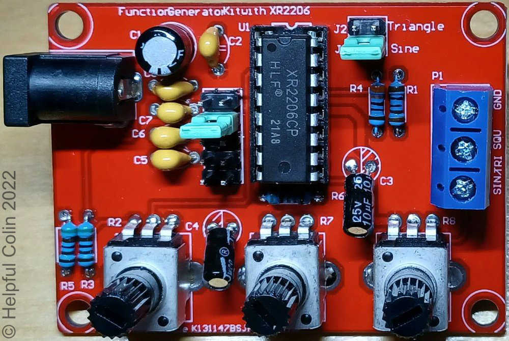
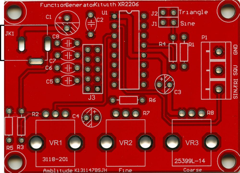
1. XR2206 Function Generator Component Layout Diagram
The original component layout diagram is satisfactory and is almost identical to the image printed on top of the circuit board. So I have photographed the circuit board to display here instead.
2. The Function Generator Component Table
Below I have produced my own table listing the components with their description and value. For non electrolytic capacitors I have also listed the code printed on them.
| COMPONENT | DESCRIPTION | CODE | VALUE | NOTES |
|---|---|---|---|---|
| R1 | Wire ended resistor | Brown, Black, Black, Brown | 1kΩ | Unpolarised |
| R2 (VR1) | Potentiometer | B503 | 50kΩ | Unpolarised |
| R3 | Wire ended resistor | Green, Brown, Black, Brown | 5.1kΩ | Unpolarised |
| R4 | Wire ended resistor | Orange, Orange, Black, Black | 330Ω | Unpolarised |
| R5 | Wire ended resistor | Green, Brown, Black, Brown | 5.1kΩ | Unpolarised |
| R6 | Wire ended resistor | Green, Brown, Black, Brown | 5.1kΩ | Unpolarised |
| R7 (VR2) | Potentiometer | B503 | 50kΩ | Unpolarised |
| R8 (VR3) | Potentiometer | B104 | 100kΩ | Unpolarised |
| C1 | Electrolytic capacitor | NO CODE | 100μF | Polarised Long wire is +ve |
| C2 | Ceramic capacitor | 104 | 0.1μF | Unpolarised |
| C3 | Electrolytic capacitor | NO CODE | 10μF | Polarised Long wire is +ve |
| C4 | Electrolytic capacitor | NO CODE | 10μF | Polarised Long wire is +ve |
| C5 | Ceramic capacitor | 105 | 1μF | Unpolarised |
| C6 | Ceramic capacitor | 473 | 47000pF | Unpolarised |
| C7 | Ceramic capacitor | 222 | 2200pF | Unpolarised |
| C8 | Ceramic capacitor | 101 | 100pF | Unpolarised |
| U1 | Integrated Circuit | XR2206CP | Notch is between P1 & P16 | |
| JK1 | Power Socket | NO CODE | 5.5mm Outside × 2.1mm Inside | |
| J1-J2 | Header Pins & Cap | XM2.54 | 2×2pin | For Changing Waveform |
| J3-J7 | Header Pins & Cap | XM2.54 | 5×2pin | For Changing Frequency Range |
| P1 | Output Connectors | 3×1term. | Screw Terminal |
3. Soldering Instructions

- The components are fed from the front of the circuit board (the side with the writing on.) Start with the smaller less sensitive components listed here. After pushing them through their holes splay out their wires to hold them in place while the board is turned over and soldered:
- Resistors (bend their wires at right angles near to their bodies),
- Ceramic Capacitors,
- Electrolytic Capacitors.
- Solder:
- The IC Socket (align the notch in one end with the picture on the circuit board,
- Blue Terminal Block (ensure the connection holes face the edge of the board,
- Power Socket,
- Potentiometers.
- After soldering, at any stage, cut the unnecessary wires off as close to the board as possible. Any bits that protrude will make the total height of the board and components so big that the lid (front panel) won’t fit. I discovered this the hard way. The tabs on the potentiometers and the power socket must be bent to lie flat. I have acquired small wire cutters which sit very flat against the board and have a spring to open them especially for this work. You can see them below:

4. Debugging Stage
- After completion of soldering insert the IC (XR2206) into its socket. Observe its polarity by looking for the notch in one end and align that with the notch in its socket. Also try and take anti-static precautions while doing this. The pins 1 to 8 may need to be straightened and pushed towards pins 9 to 16 to reduce the distance between them. There are plastic tools available to assist with this.
- Connect a 9v to 12v power supply (or battery) to the power socket JK1. JK1 is a standard low voltage power jack with an outer sleeve 5.5mm dia. and a centre pin dia. of 2.1mm NOTE: The centre pin is the +ve connection and the outer barrel is the -ve connection.
5. Using The XR2206 Function Generator
- With the Jumper Cap (link) in the J1 position the XR2206 Function Generator will produce a Sinewave output at the blue terminal of P1 labelled SIN/TRI.
- With the Jumper Cap (link) removed from J1 position the XR2206 Function Generator will produce a Triangular wave output at the blue terminal labelled SIN/TRI. When choosing this setting the Jumper Cap (link) can be placed in the J2 position to retain it so it doesn’t get lost. The pins at the J2 position are not connected to any part of the circuit.
- A Square Wave output is always available at the blue terminal labelled SQU. The mark to space ratio is not adjustable using this kit as provided.
- The AMP (Amplitude) control adjusts the amplitude of the Sine and Triangle wave outputs only. (“See Distorted Sine Wave” produced when the amplitude is set too high in the “Examples of The Waveforms Produced” below.) NOTE: This control is wired in reverse to what is normally expected, such that a clockwise movement DECREASES the amplitude and an ANTICLOCKWISE movement INCREASES the amplitude. When turned to maximum the sinewave output is very distorted. This can be checked with an oscilloscope.
- There is NO amplitude control for the square wave output. The amplitude is approximately 10.6V Peek to Peek from the one I’ve measured here (see the 4kHz square wave image below).
- The COURSE control adjusts the frequency generated by large increments.
- The FINE control adjusts the frequency generated by small increments.
- The Jumper Cap (link) J3 can be placed on the 2⨯5pin block in any of the five positions to change the frequency range covered by the COURSE and fine controls. The frequency ranges available are marked on the transparent cover and are:
- 1Hz – 10Hz,
- 10Hz – 100Hz,
- 100Hz – 3kHz,
- 3kHz – 65kHz,
- 65kHz – 1MHz.
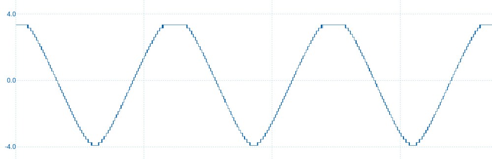
Examples of The Waveforms Produced
The waveforms below have been reproduced with the aid of a PicoScope 2206B MSO. (The Y scale is in Volts.)


6. The XR2206 Function Generator Kit Schematic Diagram

NOTE: The two Jumper Caps (links) in my diagram are plugged onto the pins of header blocks J1-J2 or J3-J7. In each case the link is shown by a dotted line between two pins. Running along the middle of each header block is an arrow. The tail of the arrow is at the lowest Jumper Cap position and the point is at the highest Jumper Cap position. The original instructions only refer to J1, J2 & J3. My instructions continue this numbering to J7 to describe the five positions their J3 can be placed in.
If the kit was more sophisticated it would replace J1-J2 with a single pole two way switch and J3-J7 with a single pole five way switch.
Leave a Reply