Introduction
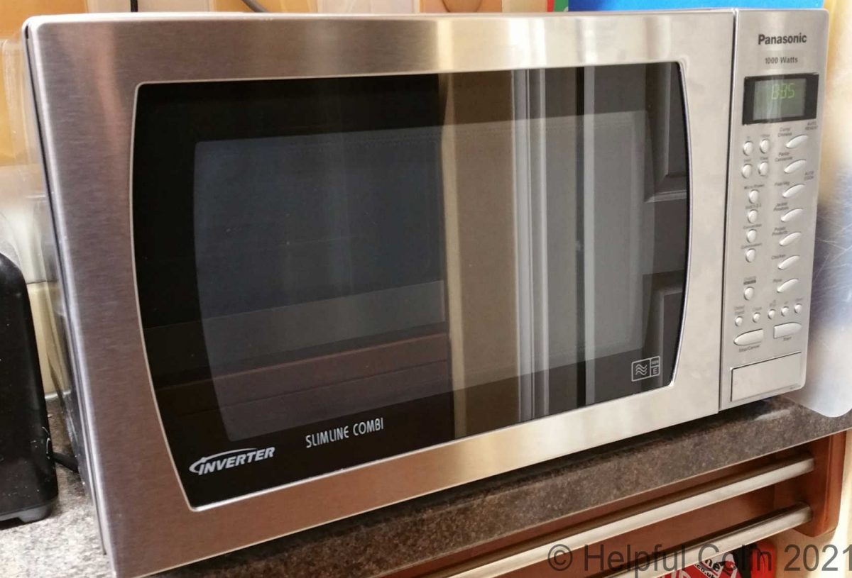
A few months ago my eleven year old Panasonic 1000 Watt Slimline Combi Microwave Inverter (Model: NN-A574SBBTQ) developed a problem which was only visual. The large rectangular button used to open the door began protruding on the right end by about five millimetres. Operation of the machine wasn’t impaired but continuous use with the faulty button led to further problems when the button jammed and I couldn’t easily open the door. In the end I had to make microwave inverter repairs to the door opening button and to the door bezel when it later came adrift.
Safety Notice
Microwave Ovens are manufactured to high safety standards, particularly because the microwave radiation generated within would be very dangerous to anyone nearby if it escaped.
Because of these dangers microwave ovens must NEVER be operated with the door open or the outer casing removed.
This means they must ALWAYS be disconnected from their source of power (the mains) when being worked on with the cover off. This is not only because of the dangers from high voltages but to prevent bodily damage caused by microwave radiation.
Any testing during or after a repair must wait until the microwave oven is reassembled with the casing on and the door shut. Electronics engineers may test other devices like computers and TVs safely while disassembled with parts exposed, but that would be TOO DANGEROUS with microwave ovens.
Getting The Door Open
I found that if I pressed hard enough on the jammed door opening button, and pulled on the bottom edge of the door at the same time, I could force it open. The action of closing the door worked as normal.
Operating the door like this went on for a couple of weeks. Then, Whilst pulling the edge of the door to force it open, the bezel (which is what I was really applying the force to) around the edge of the door glass came away.
The First of My Microwave Inverter Repairs Was To The Door Bezel

The bezel (shown pink in Fig. 1) is just a rectangle of pressed stainless steel held onto the edge of the door with double sided sticky tape. As I have seen before with double sided tape, the central padded portion separating the two sticky surfaces had split leaving one sticky surface adhered to the door and the other to the bezel.
At this moment I realised I would have to make the first of my microwave inverter repairs. Unfortunately for readers I got on with the job and failed to take photographs of the work at the time. So I have little to show here.
Cleaning The Old Sticky Tape Off The Bezel
Having decided to replace the the tape (a black fibrous substance with adhesive on both sides) I spent some time removing it. I rolled it up with my finger tip by pushing on it at a 45° angle. This can be tough on the fingers. The process attempts to pull the skin away from under the finger nail. I helped the process along with some Sticky Stuff Remover® (available from many stores). That soaked through the remaining tape body and dissolved the adhesive. A rag soaked in it removed all remaining adhesive when I rubbed it vigorously. I followed that with a damp rag and a dry rag to clean both surfaces ready for the new tape.
Re-sticking The Bezel To The Door
I had planned to replace the tape with double sided carpet tape. I still think that was a good idea but I hadn’t got any. Then it came to me to use some GORILLA® HEAVY DUTY MOUNTING TAPE which I already had. This tape already had the correct width.
The procedure I used for sticking the bezel on the door:
- It was important to determine the correct orientation of the bezel. The corners on the hinge end are rounded but they are square at the catch end.
- With the inside of the bezel facing upwards I laid it on the table.
- I cut strips of Gorilla Tape to match the length of each side and stuck them down to the inside of the bezel.
- Then I peeled the backing tape off and carefully presented the bezel to the door, pressing it on firmly when in place.
This Gorilla Tape can’t be slid into place and is very permanent. So accurate positioning is paramount. However this was the easiest of my Microwave Inverter Repairs.
The Second of my Microwave Inverter Repairs Was To The Door Opening Button
The Fault With My Microwave Inverter Door Opening Button
On the right of the door of this microwave inverter is the Control Panel. The door opening button is a rectangular plastic moulding which sits in an aperture at the bottom of this panel. Normally it’s pushed out by a spring until it lies flush with the panel and can be pushed in by fingers to open the door. So operating it is like pushing a rectangular piston into a box.
With mine a fault had developed, as mentioned in the introduction, causing the right-hand end of the button to protrude by about 5mm. At the time I didn’t know why it stuck out and for a while it wasn’t a problem so I just used it as normal. The fault didn’t affect anything other than the machine’s looks.
How And When My Microwave Inverter Door Opening Button Jammed
On investigation the fault was caused by the retaining clip at that end of the button breaking away from it. The eventual jamming of the button was caused by that loose clip falling into the button’s housing cavity behind the button and getting in the way of the button’s movement.
The jamming up happened after I took my first look inside the microwave to see how I might repair the protruding button. At that time I didn’t know exactly how the button was constructed or how to dismantle the Control Panel. So I couldn’t see an easy solution and put the cover back on with a plan to continue using it in its slightly faulty state. I suspect manoeuvring the microwave into a variety of attitudes while doing this let the small plastic clip fall into the button’s cavity. As you can see from Fig. 10 it could have fallen out and away from the cavity as an alternative.
Safety Warning
This is the point where I’m going to begin describing how I took the Outer Case off to perform Microwave Inverter repairs. So if you are thinking of doing the same I want you to be well aware of the dangers involved. If you just skipped over my Safety Notice following the introduction please go back and read it now. Also bear in mind that metal edges of steel covers can be razor sharp and can cut hands and fingers.
During Microwave Inverter Repairs I Removed The Outer Case
The Outer Case is held on by four screws at the back. But fixed over it is a pressed steel spacing panel. This keeps the machine away from any wall or objects it might be pushed up against and maintains ventilation of the back panel. The steel panel is held in place by two Torx® screws whose heads require a hexagonal star patterned drive bit to free them of the type:
CR-VT-20 ![]()

When unscrewed the the top of the spacer panel, shown in Fig. 2 must be hinged down to the work surface (it’s not actually on hinges) and unhooked at two points along the bottom edge.
At this point the four Phillips® screws holding the Outer Case on can be accessed along the bottom of its back edge as indicated in Fig. 3 below.

Note: The stainless steel Outer Case is very springy so that when the screws are removed the sides spring open. You can see the effect in Fig. 3 above.
When the four screws holding the Outer Case on are removed and the sides have sprung outwards the Outer Case can be pushed/pulled back and lifted off.
How The Control Panel Is Held In Place
The parts inside the microwave are very compact and it’s not possible to work behind the Control Panel without detaching it from the chassis.
The Control Panel is fixed to the chassis by two screws, see Fig. 4, and seven plastic hooks. The two screws are adjacent to each other and at the top on the inside. The left screw (in Fig. 4) might be Posidriv® but the right is Phillips®. They pass through the chassis from behind and screw into threaded holes. The left hole, as seen in Fig. 8, has a thread tapped in the metal bracket holding the brown circuit board, but the right hole, also in Fig. 8, has a thread in the plastic of the Control Panel. So that screw serves to clamp the metal bracket between the chassis and the Control Panel.

The hooks are moulded onto the plastic frame of the Control Panel. Two hook into slots on the bottom edge of the chassis, and then five (three on the left and two on the right as viewed from the front) hook through slots in the chassis as the Control Panel is slid down into place. See the slots for these hooks in Fig. 5 below.

Removing The Cooling Fan To Access The Screws

Access to the screws is impeded by the fan cooling the electronic components. It’s turned by an induction motor mounted immediately behind the Control Panel. That fan has an elastic rubber belt driving a circulating fan in the cooking compartment too. The belt has to be removed before removing the fan. See Fig. 6.

I decided to try and remove the plastic cooling fan, shown in Fig. 7, from the motor spindle. That was easier said than done, but I did succeed. Its just wedged on and held by friction. The spindle has a flat side ground on it (see the enlargement in Fig. 6) which prevents the fan rotating on the spindle – well almost. I found I could rotate it by a very limited amount when I held the spindle tight with pliers and held the plastic in my hand. I turned it one or two degrees back and forth and pulled at the same time. The turning back and forth broke the grip of the static friction which allowed it to be pulled up a little at a time.
Detaching The Microwave Inverter Control Panel

Once the fan was removed I found it very easy to undo the two screws and unhook the Control Panel by lifting it up and pulling it forwards.
The Control Panel has two circuit boards fixed to it with components to handle output to the display and input from the buttons. Electrical connections are made by four coloured plugs and sockets with varying numbers of pins and wires which are:
- RED 2 of 3 possible pins and 2 wires,
- WHITE 3 of 4 possible pins and 3 wires,
- BLUE 3 of 3 possible pins and 3 wires,
- WHITE 5 of 9 possible pins and 5 wires.
Disconnecting these four electrical plugs frees the Control Panel completely.
Accessing The Door Opening Button

The button has three protuberances at the back which pass through holes in the Control Panel moulding. The two outer protuberances operate a plastic Bell Crank, see Fig. 9, which passes on movement, at the business end, to operate the power switch and interact with the door safety catch. The Bell Crank engages the other parts when the Control Panel is fixed in place.
In Fig. 9 the Control Panel is lying face down on a table and the view is taken from a point normally below the button looking towards the top of the panel in the distance. The Bell Crank normally hangs down in the working position due to gravity besides any pressure from the levers it has to engage.
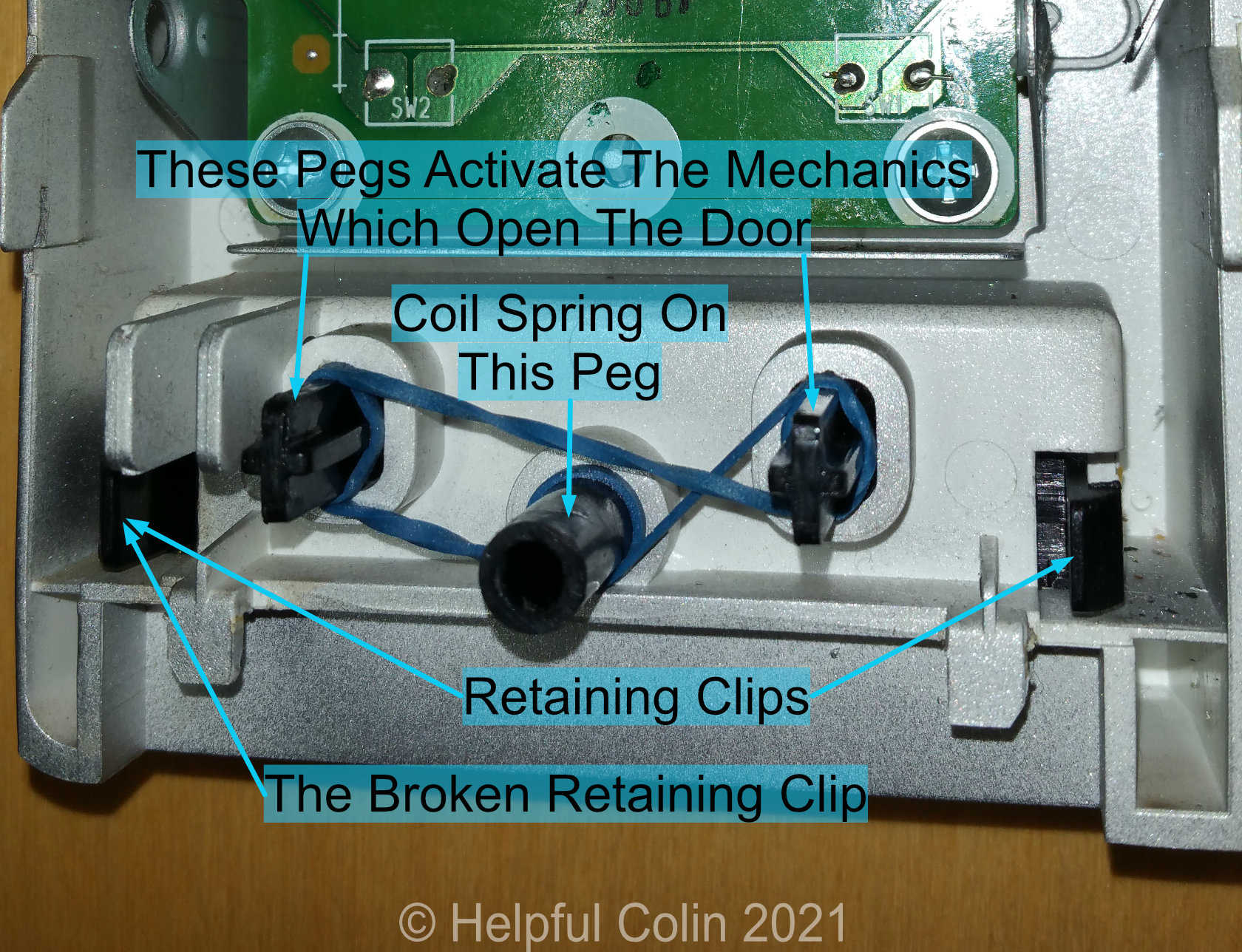
The picture in Fig. 10 shows an elastic band wrapped around the protuberances. This is a temporary measure to hold the button into its housing against the pressure of an ejecting spring. That spring is mounted on a cylindrical hollow protuberance moulded to the centre of the button. The spring fits between the button and the front side of the Control Panel to return the button to its normal position. The spring can be seen in Fig. 11 (a picture of the repaired button).
Microwave Inverter Repairs I Made To The Door Opening Button
Removing The Microwave Inverter Door Opening Button
The button is held in the recess containing it by two clips interacting with detents moulded on the plastic of the Control Panel, one at each end. The problem was due to the clip on the right hand end snapping off. It eventually settled in a jamming position preventing the button being pressed in completely. I just had to squeeze the other clip towards the centre of the button to release it from its detent allowing the spring to push it all the way out.
My First Attempt To Repair The Door Opening Button
I made a vain attempt to stick the broken clip back on the button with superglue. It stuck well but the area of adhesion was very small. I managed to reassemble it without it breaking off again but unfortunately it soon broke in use.
I realised that if the centre of the button is pressed then the button remains square in the recess as it moves in and no particular force is applied to the two catches. However if the button is pressed near to one end it twists in the recess so that a sideways force is applied to the clip at the opposite end. It is this force which must have broken the clip in the first place.
The clips need to be a little flexible since they require squeezing together to insert the button into its recess in manufacture.
My Second Attempt To Repair The Door Opening Button
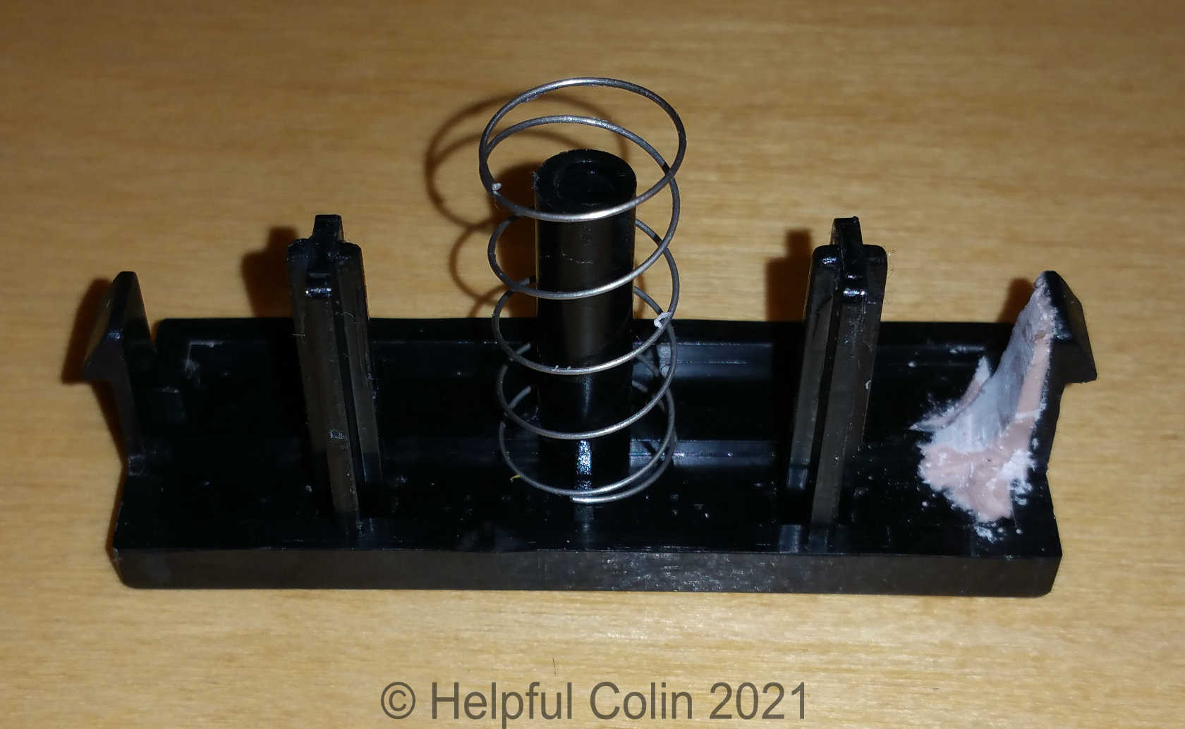
On my second attempt at repairing the button I chose to reinforce the back of the clip with P38 polyester resin (see Fig. 11).
This is how I repaired it:
- I roughened the surface of the clip and the button near to it,
- Stuck the clip to the button with superglue,
- Applied a blob of P38 to the back of the clip and surface of the button,
- After the resin set I gently worked on it with a pen knife to carve away some of the resin so that the resined clip would fit through its location hole.
Reassembling After Making Microwave Inverter Repairs
Putting The Button Back Into The Control Panel
After applying the reinforcing resin to the broken clip it becomes too stiff to bend. So I had to insert the button into it’s recess by bending the other clip only. This is a delicate procedure. Any over squeezing may cause the unbroken clip to break which may result in the button requiring a complete makeover. Fortunately I was successful.
Reattaching The Control Panel To The Chassis
While holding the Control Panel in front of and near to its location on the chassis I reattached the four coloured plugs to it. Then I aligned the seven hooks with their location points on the chassis and hooked the Control Panel in place by sliding it down into its slots. I had to check if I had trapped any wires before screwing it in place with the two adjacent screws shown in Fig. 4.
Replacing The Cooling Fan On The Motor Spindle
Whilst holding the spindle with pliers, and aligning it with the fan hole, I wiggled the fan and pushed it onto the spindle. Then I refitted the elastic drive belt to the other fan.
Replacing The Microwave Inverter Outer Case
I had to be careful not to cut my fingers on the stainless steel Outer Case when handling it. Especially because it is springy by nature and tends to move out of position until some screws are applied to restrain it. See Fig. 12.

As you can see in Fig. 12 the Outer Case has tabs which tuck under the front edge of the whole front of the Microwave Inverter. These constrain the case so it hugs the front of the machine by tucking under its front edge.
The rear edge of the case has a flange with screw holes which fits snugly to the back panel. In practice there are more screw holes than screws.
When fitting the Outer Case it can be difficult tucking the tabs under the front edge of the chassis due to its springiness. It could require two people to refit the Outer Case to avoid injury.
Fig. 3 shows all the screw holes used on the back panel. I put the Outer Case back on with the four Phillips® screws first, then the Spacer Panel with the two Torx® CR-VT-20 screws after I hooked it in place on the bottom edge. I finished by checking the tightness of all the screws.
Finally
I just had to test that the Microwave Inverter Repairs worked satisfactorily.
NOTE: Although this microwave inverter model: NN-A574SBBTQ is obsolete similar models are still available.
Leave a Reply