Post Description
How I replaced an incandescent bell push light with LEDs. The bell push operates a door chime powered by AC from a bell transformer.
Introduction
I had a Friedland Door Chime with its original illuminated Bell Push light until I converted it to LEDs. Originally it used a “festoon” bulb (a type of incandescent lamp). That’s much like a fuse to look at, i.e. a cylindrical glass tube with a filament stretched between two metal end caps. The end caps are where the electrical connections are made. In practice these connections are in the form of clips which also hold the bulb in place.
Pic. 1. A Festoon Bulb Form of Incandescent Lamp


An incandescent lamp has a limited life and eventually burns out. These particular lamps aren’t cheap (now available on 06/12/2020 at £18+p&p for two) and are awkward to replace. So when white LEDs, which have a greater life expectancy, became available I used them to replace the lamp.
NOTE: It’s cheaper to buy a new Light Spot Illuminated Door Bell Push for £3.30 (on 06/12/2020) than buy the old Friedland D70 replacement lamps.


Electrical Safety While Working On The Bell Push Light
Door bells run off a low voltage supply, either using AC from a mains transformer or DC from batteries. The voltage isn’t likely to be more than about 20 volts. So the voltage used to operate the bell is safe.
If a transformer is used then the danger comes from the primary side (the mains side). Anyone connecting the mains side of a transformer must be competent to do so. Ideally it needs to be wired through an isolation switch.
Door bell’s consume a low level of energy so they can be connected to a lighting circuit fused at 5 amps (or a 6 amp RCD). A light switch makes a suitable isolation switch. Else they can be connected to a fused spur (with a 3 amp fuse) off a ring main or they can be cabled to a mains plug with a 3 amp fuse.
Working on the secondary side (the low voltage side) is safe as long as the transformer is in good condition.
NOTE: If there is a transformer fault there can be a breakdown of insulation between the primary and secondary winding. This can make the secondary side become live and dangerous.
Bell transformers should be well made because they are expected to be permanently connected to the mains for years, just as mine has been. So they shouldn’t get too hot and become a fire hazard.
Basic Operation and Bell Push Light Circuitry
My Door Chime gives a “Ding-Dong” sound when the core of a solenoid strikes two vertical chime bars. It strikes one when it is driven through the solenoid by a magnetic field, and the other when the power is cut and the field collapses. It then returns and overshoots its starting position until it strikes the chime bar driven by a spring. Finally after bouncing off the second chime bar it rests where it started not touching either bar. By keeping from resting against either chime bar it doesn’t deaden their ring.
The electric circuit is simple. The solenoid and the bell push are in series across an AC supply from a transformer. Pressing the bell push completes the circuit letting current flow through the solenoid until it is released.
Pic. 2. Typical Schematic Diagram of A Door Chime With Illuminated Bell Push

The original lamp is wired in parallel with the bell push. So current continually flows through the solenoid and lamp before the bell push is pressed. That current is sufficient to illuminate the lamp but not sufficient to operate the solenoid.
S1 is the mains isolation switch on the primary side of the bell transformer.
NOTE: This method was used for years in the days of incandescent lamps. It allowed a bell push to be illuminated and signal to a bell using a 2-wire interconnecting cable.
Converting A Bell Push Light To LEDs
I had to take into account the space available inside the Bell Push when I converted it to use LEDs. I was able to squeeze 4 × white LEDs in the space and lay them near the translucent edge where the light could best shine out and indicate its presence. My white LEDs are slightly yellow. This may be due to them being under powered.
Let me remind readers: The door chime has an AC (Alternating Current) power supply. This is OK for a solenoid and an incandescent lamp but NOT OK for LEDs. LEDs require DC (Direct Current) for the most part. This is because they may not withstand even medium reverse bias potentials. They do of course require a current limiting resistor in series with them too.
NOTE: LEDs can be damaged by reverse bias potentials in excess of 5V.
I resolved the AC problem by wiring the LEDs in parallel pairs so that each was the opposite way around to the other. The voltage across the reverse biased LED will only be the forward bias voltage of the other LED (typically 1.8 to 3.3 volts) and that will not damage it. Time has upheld this view as they continue to work after several years.
Why Not Use Batteries?
Batteries provide a DC supply and would remove any concerns about using AC. Well I didn’t want to find I had flat batteries in my door bell just when I expect an important delivery. That’s the main reason.
You can’t use batteries to power a door bell with an incandescent lamp in the bell push. That really would run the batteries down quickly. With LEDs, well I hope they would last much longer. That would be an interesting experiment to find out how long they would last.
The Schematic Circuit Diagram
The circuit diagram below shows the Bell Push LED schematic with the 2 wire cable connecting it to the bell box terminals 1 & 2.
Pic. 3. LED Illuminated Bell Push Schematic

Across the bell push contacts is a series chain of components. It consists of two pairs of parallel LEDs in series with a 240Ω current limiting resistor. Each LED forming a pair has its cathode connected to the other’s anode. This circuit lights two out of four LEDs on each half cycle of the mains. Each forward biased LED protects its paired LED from a reverse voltage.
LEDs only light up when they are forward biased. So the two that are reverse biased on any half cycle will not be lit at that time.
The LEDs noticeably flicker with a 50Hz rate but they light the button well in the dark.
The Physical Construction
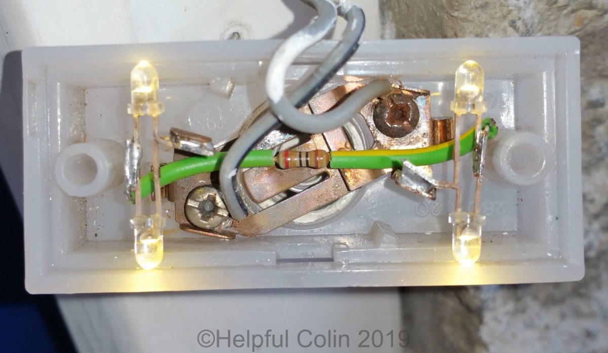
Here is a picture looking inside the back of the Bell Push after modification.
Pic. 4. Inside THE LED Illuminated Bell Push

The two wire cable terminates under the screw heads of the screws which hold the two spring contacts of the bell push in position. Each LED forming a pair has its cathode soldered to the other ones anode. Then each pair has one of its contacts soldered to an old lamp contact and the other to the 240Ω current limiting resistor. That resistor is the component which has the green sleeving on in the picture.
Compare the wiring in Pic. 4 with the schematic diagram in Pic. 3 to get a better understanding. In both, the connections and components are similarly labelled.
Installation of The Original Bell Push Light
The picture below shows how the original lamp was located. Wedged between spring clips, which are part of the bell push contacts, and protrusions in the plastic case.
Pic. 5. Example With Original Lamp

How The Bell Push Light Looks In Situ
I cannot demonstrate the bell push illuminated by the old style lamp because I don’t have a lamp and I would have to dismantle the LED arrangement to plug it in.
Below in Pic. 6 you can see the LED illuminated bell push without the final black cover.
Pic. 6. The Bell Push Mounted Without The Black Cover

This video of the bell push shows an exaggerated flicker caused by the LEDs being fed with 50 Hz AC. That 50Hz is then beating with the frame rate of the camera to give a much slower flicker frequency.
Video 1. The Bell Push Illuminated By Flickering LEDs
See How I Extended My Door Bell
I’ve since extended my door bell/chime. Now I can hear it in my house extension and in my shed. Here is a post describing how I did it using wireless technology: Extending The Door Bell In My Home.
In spring of 2023 I replaced the original bell push with a Ring video door bell camera. This type of camera and button is made to run from a 12V AC supply and operate an old fashioned door bell correctly.
Leave a Reply