You may notice how the indicator light in your mains sockets and switches dims with time and wonder why. These lights are usually small neon bulbs which glow when a small alternating current of 1 or 2mA passes through them. These bulbs are filled with neon gas which glows red when a current passes through it. There is no filament and no heating element. Neon is an inert gas which glows with an orangey red colour in these bulbs. If the current is too high or the electrodes are made of an unsuitable metal the metal evaporates from the surface of the electrodes and condenses on the inside of the glass bulb, making it opaque, so the light output dims as the glass gets covered.
When this happens the only solution is to replace the bulb. They only cost 30p and can last many years, even when they are on all the time, unless, as above, too much current flows through them.
Right: Another use for these neons – as a night-light (cover removed). This is a light the size of a mains plug with two neons in it which have a translucent cover and shine on the floor area near my bathroom. They light the way at night when all other lights are off.
These particular ones were replaced some years ago and have not gone black again. The reason they haven’t gone black is because I changed the resistor (increasing it to 100kΩ). Sorry I can’t remember its previous value. Now the current is 1.15mA.
Now I’ll get back to my original problem: changing the bulb in a 45A 250V Isolating Switch.
Safety Notice
Because only qualified persons are allowed to work on Mains Wiring I will not discuss the removal or replacement of a switch like this within the Mains Wiring of any premises in this post. All my discussion relates to work on a bench under workshop conditions. All individuals must make provision for their own safety and not do anything that may endanger the safety of others.
Isolation Switch Neon Indicator Replacement Process
Right: Here are the innards of the Mains Isolation Switch on the bench. On the left is the neon indicator under a red translucent cover and in the centre is the rocker switch. Observing the plastic cover will reveal how it clips in place. Note how it holds the neon in situ.
Right: The neon glowing dimly with the cover removed. Compare it with the brightness after the repair at The Testing Stage further down the page.
Right: I have turned the switch over so you can see how the wires from the neon are inserted into the back of the switch (the ones on the left covered in yellow sleeving). The bare wire just pushes into the holes adjacent to the screw terminals for the main wires. In the holes the wires are held by brass springs pressing them against the sides of the holes. Consequently the neon’s wires can be pulled out to release it.
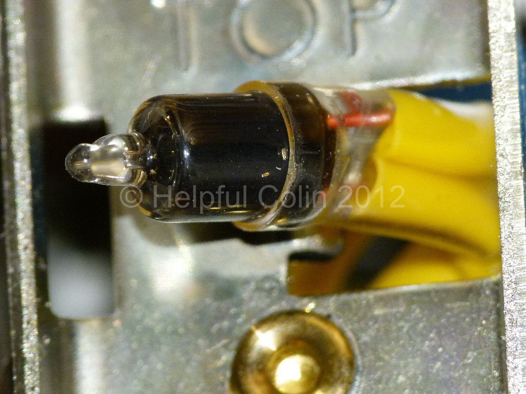
Right: The blackened neon with the sleeving removed from the wires exposing the current limiting resistor. This is already a high enough value at 270kΩ limiting the current to around 0.7mA. (I tested the value of the resistor with an ohmmeter.) The voltage drop across this neon is about 60V leaving 180V across the resistor. From Ohm’s Law (I=V/R) the current through the neon and resistor is 180/270,000. This equals 0.66mA.
Going back to my Introduction to this post I have to ask, “Why has this neon gone black?” Since the current is sufficiently low. Perhaps the electrodes were made from an unsuitable metal.
Right: The old neon is clamped in a small vise with rubber glued to the jaws to give a soft grip. This is ideal for holding the neon while I unsolder the resistor from one leg and the extension wire from the other. The extension wire is used to make the other leg as long as the one with the resistor.
Reassembly with the new neon was the reverse of this procedure.
Right: The Testing Stage. Compare the brightness with the previous picture of the neon glowing dimly.
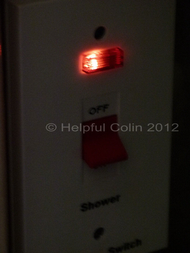
Right: The Mains Isolation Switch Neon Indicator replaced and the switch back in use with a nice bright light for all to see.
7 responses to “Changing A Mains Isolation Switch Neon Indicator”
Roger Button
Thanks for the tips on replacing the neon bulb. Can you suggest where I can buy the replacement bulb? Maplin and other local suppliers don’t seem to do them any more.
There is a Radio Shop in Derby called R. F. Potts, 68 Babington Lane, Derby, DE1 1SX, Tel. (01332) 343469. I highly recommend this shop which has been selling new and 2nd hand electronic components and equipment since WW2 at least. Well before either Radio Shack or Maplin’s were on the scene. Else search the internet for a “neon indicator lamp”. I found this when I Googled it: http://uk.farnell.com/jsp/displayProduct.jsp?sku=1139250&CMP=KNC-GUK-FUK-GEN-LISTINGS&gross_price=true&mckv=MGdGvzqH
In my post I quote the current through a neon and series resistor as 0.66mA. The applied voltage is 240V AC RMS. So the power used is 0.1584W shared between the neon and resistor. This is a small amount of electricity. It would take 6,313 hours to us up 1 unit (1kWH). I am confident that you will dissipate so much energy while you carry out the work that you will spend more on the food required by you than the electricity cost saved. You will also warm up the earth with your body more doing the work than leaving it alone and using your time more efficiently on a more rewarding project. We together have probably already used up too much energy and warmed up the earth too much just considering the problem.
The neons together with their resistors can be removed without ill effect but it will probably detract from your property value. My advice is: Use the washing line and not the tumble dryer; use the microwave and not the oven and only boil as much water in the kettle as you need.
Hi I have purchased 3 trendiswitch fused spur but what I thought was a light is in fact a knockout for a cable to be wired in is it possible to attach a neon light and place the light in were the knockout hole is
We use cookies on our website to give you the most relevant experience by remembering your preferences and repeat visits. By clicking “Accept”, you consent to the use of ALL the cookies.
This website uses cookies to improve your experience while you navigate through the website. Out of these, the cookies that are categorized as necessary are stored on your browser as they are essential for the working of basic functionalities of the website. We also use third-party cookies that help us analyze and understand how you use this website. These cookies will be stored in your browser only with your consent. You also have the option to opt-out of these cookies. But opting out of some of these cookies may affect your browsing experience.
Necessary cookies are absolutely essential for the website to function properly. These cookies ensure basic functionalities and security features of the website, anonymously.
Cookie
Duration
Description
cookielawinfo-checkbox-analytics
11 months
This cookie is set by GDPR Cookie Consent plugin. The cookie is used to store the user consent for the cookies in the category "Analytics".
cookielawinfo-checkbox-functional
11 months
The cookie is set by GDPR cookie consent to record the user consent for the cookies in the category "Functional".
cookielawinfo-checkbox-necessary
11 months
This cookie is set by GDPR Cookie Consent plugin. The cookies is used to store the user consent for the cookies in the category "Necessary".
cookielawinfo-checkbox-others
11 months
This cookie is set by GDPR Cookie Consent plugin. The cookie is used to store the user consent for the cookies in the category "Other.
cookielawinfo-checkbox-performance
11 months
This cookie is set by GDPR Cookie Consent plugin. The cookie is used to store the user consent for the cookies in the category "Performance".
viewed_cookie_policy
11 months
The cookie is set by the GDPR Cookie Consent plugin and is used to store whether or not user has consented to the use of cookies. It does not store any personal data.
Functional cookies help to perform certain functionalities like sharing the content of the website on social media platforms, collect feedbacks, and other third-party features.
Performance cookies are used to understand and analyze the key performance indexes of the website which helps in delivering a better user experience for the visitors.
Analytical cookies are used to understand how visitors interact with the website. These cookies help provide information on metrics the number of visitors, bounce rate, traffic source, etc.
Advertisement cookies are used to provide visitors with relevant ads and marketing campaigns. These cookies track visitors across websites and collect information to provide customized ads.


Leave a Reply